I have parts. Thanks David for ordering them. I have been tied up with the fire truck and plasma table, but I have not had time to do any work on it. I hope to spend an evening or two this week working on it.
3 Likes
Sorry, for the long delay. I gave up trying to reuse the existing bearing sleds with the new arms.
We ordered a new set of bearing to match the new arms. They came in yesterday. I have a few days off work for Thanksgiving holiday, so I should be able to get them mounted. I will keep you posted.
Happy Thanksgiving
2 Likes
The bearings and new arms are on the printer. it seems stiffer and less sloppy.
The replacement power supply for the rostock is reversed. I need a new part cut. It needs to fit on a 10x5 piece. The existing part is melamine that is 6.5mm, but I think 1/4" would work.
If someone happens to be up at the space and can look in the scrap pile for a piece of wood it would help out save me a trip to the space before buying a piece of wood. If you wanted to cut also that would be wonderful. I am attaching the dxf file.
power_supply_bracket.dxf (14.7 KB)
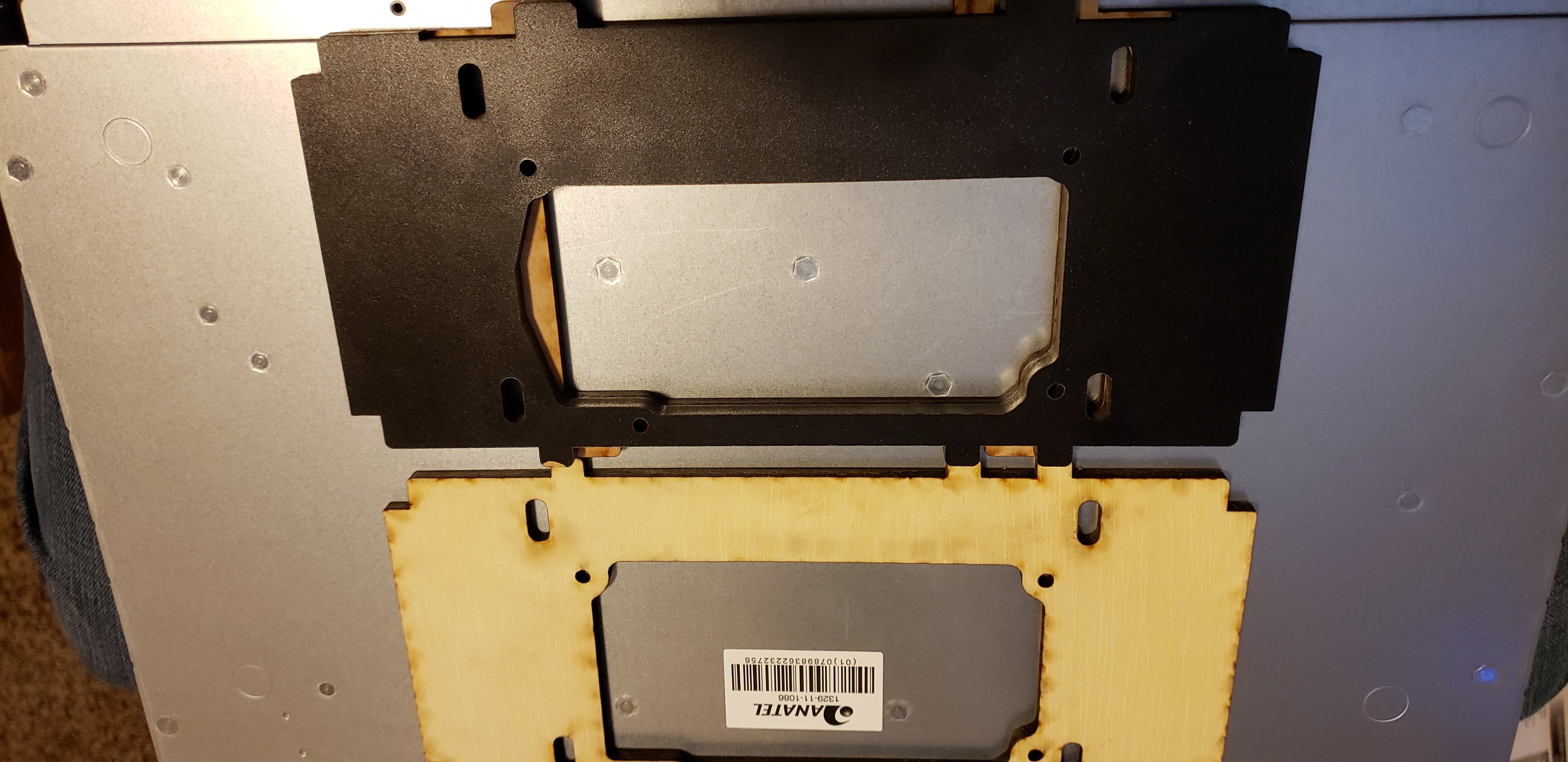
I finally had some free time to come down to the space to use the laser. Here is the new power supply adapter.
2 Likes
So close. 
The power supply was aligned to the wrong line in the drawing, so it was pushed to the top of the cavity.
It hits the heated bed wires. I will be at the space tomorrow night, so I will cut another one.
power_supply_bracket2.dxf (14.8 KB)
I remade the panel. The power supply is mounted. I have tested a circuit to allow the raspberry pi to control the power supply, so it can power off the printer after the print. I am waiting on a small solder prototype board make a final circuit board that can be mounted.
I have tested the controller, since the last power supply went bad. I still need to test the heated bed since I have stuff on it at the moment. I thought the hot end fan or wiring was bad, so I took it off to test it. Turns out I had it plugged in to the wrong port. I thought it should be in fan1 instead of heater 1 silly me. I might replace it since it is off.
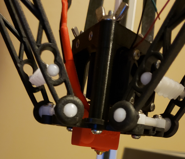
I have removed the old heater block and nozzle and mounted the new volcano hot end. The original mounting bracket was taller and volcano is rotated 90deg, so we lose about 1/2" ish of height as is mounted now. Later I will remake a new mount that is taller. Not a show stopper.
@jameslancaster @mikeb
I looked at it and it is running a very old version of marlin 1.1.0 RC8. I could not find the configs in the github. If anyone know was this the stock firmware or did someone flash it in the past? If someone did do you know where the configuration files are?
I still need to find or make a part cooling fan mount and nozzle. I need to see if the original ones I found with the old arms will work.
TODO list
Retention the belts
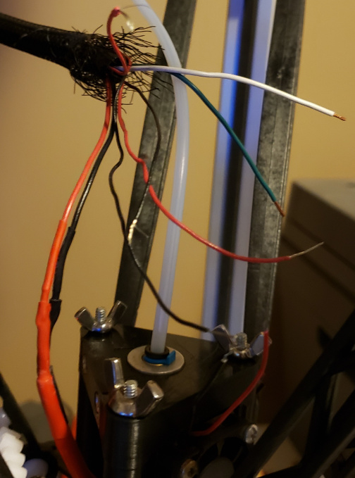
Spice in the connector for the e3d thermistor.
Reattach the hotend cooling fan.
Cram all of the parts under the bed, and route the wires.
Remount the controller cooling fan.
The part cooling fan(s) needed.
Upgrade firmware (maybe)
I hope to have a test print this weekend and bring it back to the space. Even if it is without a part cooling fan.
4 Likes
Xmas got away with me, and I did not work on it over the holiday.
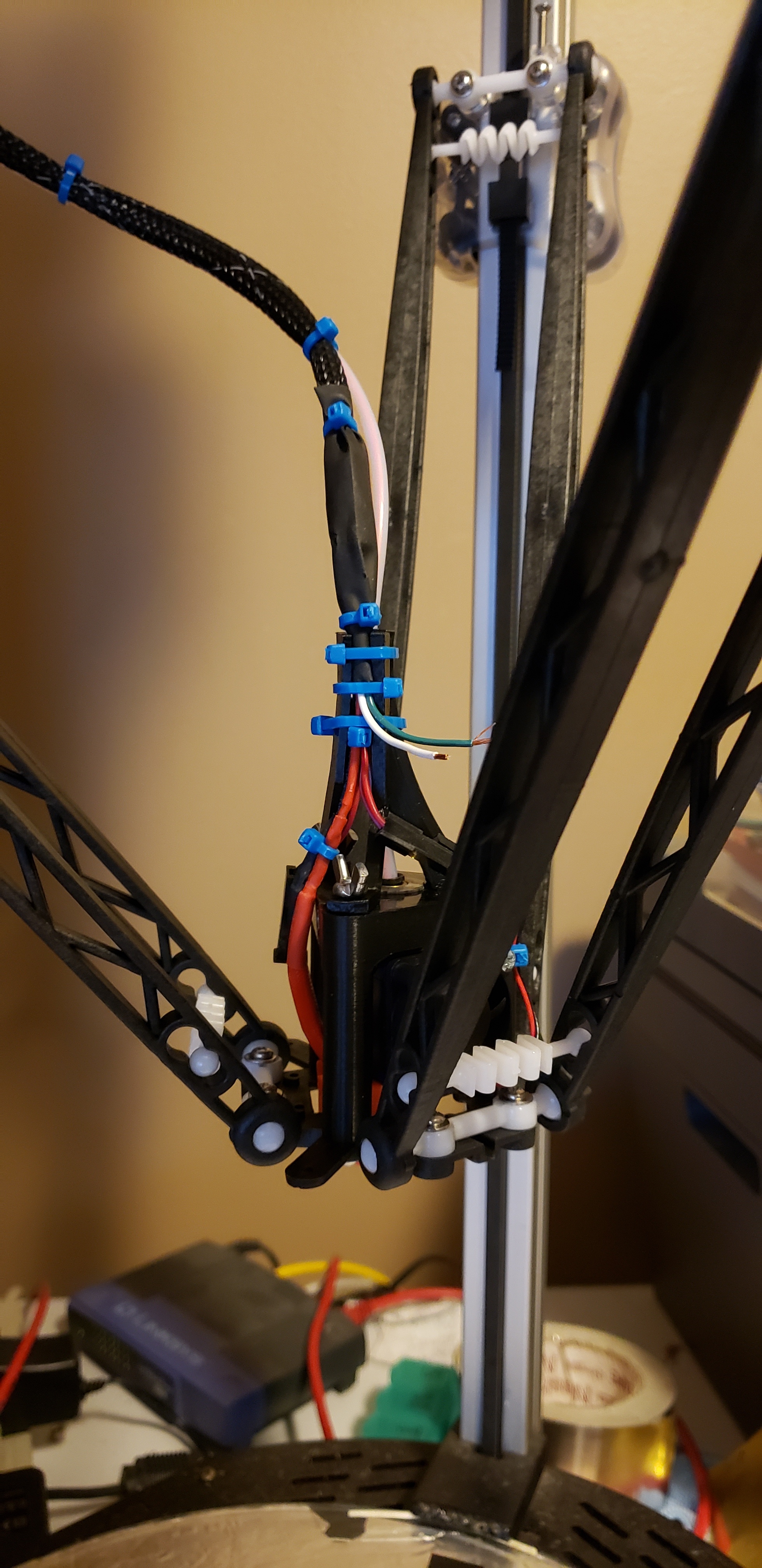
I did get some work done this weekend. i ran some filament through the new volcano hotend. the calibration is wayoff. i put the heated bed back on and tested the new wiring. i add strain relief bracket.
Since the arm length changed the firmware needs to be rebuilt/updated. i found the old firmware config file on the wiki. thanks @jameslancaster.
there were tons of formatting differences between what we had and the current marlin mostly comments and some new stuff. i have not been able to get it to compile successfully yet. it crashes and says submit a bug report. i will update the arduino studio to see if the crash goes away.
TODO list
build firmware.
Retention the belts.
Cram all of the parts under the bed. waiting on firmware.
2 Likes
Thanks for doing this Tom!
After upgrading arduino studio. It stopped crashing. I was able to generic printer config to compile for the Rambo board. Then pulled all of the changes from the original config chunk by chunk. It compiles and the printer homes, but the height is not correct.
It seem quieter, and does not slam into the z limit switches.  Enough for the day.
Calibrating a delta was a new experience, some good some bad. Not all of the information was 100% correct from the Seemecnc documents. I have the basic Delta radius dialed and the towers limit switch set, so the bed is flat and level.
One challenge is that the eeprom on the board was/is not enabled. Does anyone know if it was ever enabled? Finding information on a very old controller board for one, and the Seemecnc forum seem to be down at the moment or forever.
With the eeprom it make the calibration cycle very painful. Do something then flash the firmware. @jameslancaster @dom @mikeb Does anyone recall any information about this?
I printed a calibration cube, but since it does not have a part cooling fan yet. It is horrible. I am home sick today, so I will work on it a bit more.
I would like to add support for a filament run-out sensor ->park in the firmware, and run the wire pair up a tower while it is in the current state. If the cables and firmware are in place it can be finished up at a later date at the space.
I hope to bring it back to the space this weekend. 
your body is telling you to rest please do. We appreciate what you do but don’t overdo it.
1 Like
Tom,
I really do not remember enough about the calibration from the last time to be of much help. I don’t think I ever had to know anything about the onboard eeprom, but there have been many major mods since the one and only time I did a full calibration. I think the front panel that is not there anymore allowed fine adjustments to the leveling differently than how it is done now. And I know it gave a simplified interface for entering numbers for arm length, radius of outer pivot circle and inner pivot circle and heater PID numbers.
I used the kit assembly PDF file (800+ pages) to do both the physical and electrical adjustments. But a whole lot has been modified since then. Also, each of the Rostock and the seemecnc fora had some improved instructions for some of the steps, but neither place had all of them and there was a third place with additional good information.
Christian may be the person that did the two or three most recent calibration cycles, since he did several hardware mods and some repairs since the last time I had.
2 Likes