Sorry for this being two weeks, rather than 1, Part 1 here: FPGAs/CPLDs: Part 1: Binary Logic I In this I wanted to see about completing this part, and also having the logic display nicely, so there’s a simulator at the bottom which can be used by people using either Logisim-Evolution or the original Logisim.
So now that we have our half adder, I’ll go into why it’s called a half-adder, and why we run into trouble, namely to do multi-bit addition we run into issues. If you have anywhere a 1 1, then it will be 10, which means that the next value should have an extra 1 added to it.
Example in Decimal, if we used the equivilent and tossed the higher place:
     1  6
   + 2  7
   ------
     3  3 For just the values.
     3 13 We have to carry the one here so it becomes:

     3  3
   + 1  0
   -------
     4  3
Same thing in binary, So to each place, we actually have 3 inputs, I’ll call them X, Y, and the value from the prior: C:
     X2 X1 X0
     Y2 Y1 Y0
   + C2 C1 C0
   ----------
This pattern holds in binary or pretty much any number systems. The reason is the Carry in normal addition can be at most 1 in any base (N) number system because you can have digits adding up to (N-1)+(N-1)+1 = 2N-1 = N + (N-1) and the N is carried. Base 2: 1+1+1 = 11 (3, or 22-1), base 10 99+99, 10’s column= 9+9+1 = 19 = 210-1. Note that in normal addition, C0 is always 0, but there are cases where we’ll want to use it. The other carries are limited to 1 so is C0.
Our half adder only takes 2 inputs. So let’s look at them, with all possible inputs if we have 3 inputs.
C | A | B || Dec || Z | V
0 | 0 | 0 ||   0 || 0 | 0
0 | 0 | 1 ||   1 || 0 | 1
0 | 1 | 0 ||   1 || 0 | 1
0 | 1 | 1 ||   2 || 1 | 0
1 | 0 | 0 ||   1 || 0 | 1
1 | 0 | 1 ||   2 || 1 | 0
1 | 1 | 0 ||   2 || 1 | 0
1 | 1 | 1 ||   3 || 1 | 1
To look back at what we already have:
A | B || Z | V
0 | 0 || 0 | 0
0 | 1 || 0 | 1
1 | 0 || 0 | 1
1 | 1 || 1 | 0
Which actually covers everything if C is zero. Now, Let’s look at the bottom half. So That’s just a +1 from the top. So what if we used the result of the top, and used a half-adder to add V and C?
                    A + B      V1 + C    Wanted
C | A | B || Dec || Z1| V1|| Z2 | V2 ||| Z | V
0 | 0 | 0 ||   0 || 0 | 0 ||  0 |  0 ||| 0 | 0
0 | 0 | 1 ||   1 || 0 | 1 ||  0 |  1 ||| 0 | 1
0 | 1 | 0 ||   1 || 0 | 1 ||  0 |  1 ||| 0 | 1
0 | 1 | 1 ||   2 || 1 | 0 ||  0 |  0 ||| 1 | 0
1 | 0 | 0 ||   1 || 0 | 0 ||  0 |  1 ||| 0 | 1
1 | 0 | 1 ||   2 || 0 | 1 ||  1 |  0 ||| 1 | 0
1 | 1 | 0 ||   2 || 0 | 1 ||  1 |  0 ||| 1 | 0
1 | 1 | 1 ||   3 || 1 | 0 ||  0 |  1 ||| 1 | 1
So comparing the Wanted to our V1+C/Z2/V2, we can see that V = V2 for all values. However, Z doesn’t equal Z2. But if you look, you can see that Z is 1 any time Z1 or Z2 are. Hey, we can do an OR! Z=Z1 OR Z2. So our final setup ends up being 2 half adders and an OR gate.
So let’s expand our setup, and go back to using A and B inputs along with C, but use the Z/V+Z/V1/2 from above.
//HalfAdder 1
V1 = A & B; // A AND B
Z1 = A ^ B; // A XOR B

//HalfAdder 2
V2 = V1 & C; // V1 AND C
Z2 = V1 ^ C; // V1 XOR C

Z = Z1 | Z2; // Z1 OR Z2
V = V2; // Bit value.
So we have a full adder which takes 3 inputs and outputs a value and a carry.
Recall our Half Adder
module half_adder (
input A,
input B,
output X,
output Y
);

   assign X = A & B; // A AND B
   assign Y = A ^ B; // A XOR B

endmodule
We’ll change the inputs to add the Carry in, (C in most of our examples above), and change Z in our examples to out_carry for Carry Out.
module full_adder (
input A,
input B,
input in_carry,
output out_value,
output out_carry,
);

    //HalfAdder 1
    assign Z1 = A & B; // A AND B
    assign V1 = A ^ B; // A XOR B

    //HalfAdder 2
    assign Z2 = V1 & in_carry; // V1 AND in_carry
    assign V2 = V1 ^ in_carry; // V1 XOR in_carry

    assign out_carry = Z1 | Z2; // Z1 OR Z2
    assign out_value = V2; // Bit value.

endmodule
So we’ve got the logic, what’s missing, ah variables. Vivado has a couple of different data types, the one we are interested is kinda like wires. We can treat modules as if you had a chip. Without having to worry about power/ground. There is a rule that a wire can only be driven by one thing at a time. It’s generally also true with larger electronics, otherwise it can have some consequences ranging from nothing to magic smoke and fire. (Perhaps the most frustrating is something that is intermittently working.)
So we have the wire data type. It’s implicit in the input/output, but for Z/V1 & 2, we should be explicit. input is a wire driven by something else, and wire is driven by the logic of the module. (generally)
module full_adder (
input A,
input B,
input in_carry,
output out_value,
output out_carry, //Carry OUT
);

wire Z1;
wire V1;
wire Z2, V2; //It supports similar declarations as C.

    //HalfAdder 1
    assign Z1 = A & B; // A AND B
    assign V1 = A ^ B; // A XOR B

    //HalfAdder 2
    assign Z2 = V1 & in_carry; // V1 AND in_carry
    assign V2 = V1 ^ in_carry; // V1 XOR in_carry

    assign Z = Z1 | Z2; // Z1 OR Z2
    assign out_value = V2; // Bit value.

endmodule
So now we have it equivilent to 3 wires coming in, 4 wires between logic functions and 2 wires going out.
Wires can also be declared as multiple wires, this is very useful to go back to our example instead of Z1, Z2, V1, V2, we can declare them as IC[1:0] and IV[1:0] (Intermediate Carry/Value)
This is often called a bus.
You declare it as wire [x, y] bus_name; Noting that generally, it’s from BUS_WIDTH-1 to 0, but it doesn’t have to be, you could declare something as wire [20:10] weird_bus. Note that it also doesn’t have to be large:small, it can be wire [10:20] weird_reversed_bus. For the most part it doesn’t matter, but one nice thing is that you can assign things based on bits. Say I’ve got 4 signals coming in (wire [3:0] signals) and I only care about 2 of them, I can declare wire [1:0] cared_about then do: assign cared_about[1:0] = signals [2:1]. They can also be assigned individually, ex: assign cared_about[1] = signals[0]; assign cared_about[0]=signals[2];
module full_adder (
input A,
input B,
input in_carry,
output out_value,
output out_carry, //Carry OUT
);

wire [1:0] IV;
wire [1:0] IC;


    //HalfAdder 1
    assign IC[0] = A & B; // A AND B
    assign IV[0] = A ^ B; // A XOR B

    //HalfAdder 2
    assign IC[1] = IV[0] & in_carry; // AND
    assign IV[1] = IV[0] ^ in_carry; // XOR

    assign out_carry = IC[0] | IC[1]; // Z1 OR Z2
    assign out_value = IV[1]; // Bit value.

endmodule
Logically it gives us this:
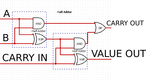
(Created using Logisim, because it’s got the symbols. Personally I hate Logic diagrams that use symbols, instead of a box with the operation in it, but it seems that everything must invent shorthand. Electronics, Math, Architechure, all seemingly for no aparent reason. Except to make it harder for people without that special knowledge. Maybe understandable when drawings were done by hand, but with computers. /rant)
Now that we have a full adder, Let’s make it add 2 bits, since, that’s the majority of the reason to have a full adder anyway. In this case we’ll be using the above module and essentially connecting wires like you would if you were using logic ICs. This will make use of the bus notation for a[1:0] and b[1:0] as inputs and out_value[1:0]. In carry will go to the first adder, the first adder’s out will go to the second adder’s carry in, and the final one will go to the out_carry for the module.
module twobit_adder (
input [1:0] A,
input [1:0] B,
input in_carry,
output [1:0] out_value,
output out_carry, //Carry OUT
);
wire Carry_between;

full_adder fa_bit_0(
  .A (A[0]),
  .B (B[0]),
  .in_carry (in_carry),
  .out_value (out_value[0]),
  .out_carry (Carry_between)
);

full_adder fa_bit_1(
  .A (A[1]),
  .B (B[1]),
  .in_carry (Carry_between),
  .out_value (out_value[1]),
  .out_carry (out_carry)
);


endmodule
There are a few ways to reference the modules, in this case, I’ll do it the way I think is the best to understand what’s connected, we could technically call it kind of like a c function, by position, eg: full_adder fa_bit_0(A[0], B[0], in_carry, out_value[0], Carry_between), but this shows what’s being connected.
When that’s processed it’s made into this: Which uses LUTs instead of gates, and since they can represent the truth tables, you only need one of them per output.
Then you can use those modules within other modules, we’ll make a 5-bit adder, out of our two bit adder and a one bit adder:
module fivebit_adder (
input [4:0] A,
input [4:0] B,
input in_carry,
output [4:0] out_value,
output out_carry, //Carry OUT
);
wire Carry_between[2];


twobit_adder two_bit_0( //TWO bit adder
  .A (A[1:0]),
  .B (B[1:0]),
  .in_carry (in_carry),
  .out_value (out_value[1:0]),
  .out_carry (Carry_between[0])
);

twobit_adder two_bit_1( //TWO bit adder
  .A (A[3:2]),
  .B (B[3:2]),
  .in_carry (Carry_between),
  .out_value (out_value[3:2]),
  .out_carry (Carry_between[1])
);

full_adder fa_bit_1( //ONE bit adder
  .A (A[4]),
  .B (B[4]),
  .in_carry (Carry_between[1]),
  .out_value (out_value[4]),
  .out_carry (out_carry)
);


endmodule
Which gives us addition. Woohoo!
Now for subtraction. If you’ve heard of signed numbers, and them going from, for example 8-bit -128 to 127 vs signed 256. So let’s look at why that is, but we’ll only use 4 bit numbers (since there are 16 of them, vs hundreds) and map them the same way, 16 > -8 to 7
Let’s use zero for zero.
(Binary) = decimal
0000 = 0
Let’s use the same numbers for 1-7
0001 = 1
0010 = 2
0011 = 3
0100 = 4
0101 = 5
0110 = 6
0111 = 7
If you note, that 4th bit gives us an easy way to test if things are negative. That’s called the sign bit for that reason.
Now we could do: that bit in front just meaning negative
1000 = -0
1001 = -1
1010 = -2
1011 = -3
1100 = -4
1101 = -5
1110 = -6
1111 = -7
But we get a negative zero and zero. Plus if we throw our negative numbers into our adder, Let’s say 0011 (+3) + 1010 (-2) We’ll get 1101 or negative -5 Which doesn’t really work. We’d have to have much more complicated logic, which had been done in some cases on early computers one example being the IBM 7090 from 1959, which along with successors was used for a lot of early computing like Mercury and Gemini at NASA. Also the first computer dating service in the US. (Gotta love the random things you learn from Wikipedia.)
So let’s look at this. How could we add 3 and -2 to get the correct answer 1
0011 + ??? = 0001
Let’s think of something else as well, say 7+ (-4), 5+ (-3)
0111 + ??? = 0011
0101 + ??? = 0010
Well, -0010 works, but we are back to how do we represent negative numbers.
So let’s start simply, How do we represent 1+(-1)=0
0001 + ??? = 0000
We can’t do that with positive numbers, because you could only get from 0001 to 10000… wait, 10000 would just be 0000 with the carry out!
So let’s let 1 be represented by 1111 and
0001 + 1111 = [1] 0000
So then, for 2 + (-2)
0010 + 1110 = [1] 0000
Let’s see if -1 + -1 = -2
1111 + 1111 = [1] 1110 dropping the carry bit, and yep.
So let’s construct the rest of them:
1111 = -1
1110 = -2
1101 = -3
1100 = -4
1011 = -5
1010 = -6
1001 = -7
1000 = -8
So we can add negative numbers and have them work, but what about subtracting positive numbers? So we’d have to turn positive numbers into negative numbers.
To refresh our whole number system. Arranged from negative to positive.
1000 = -8
1001 = -7
1010 = -6
1011 = -5
1100 = -4
1101 = -3
1110 = -2
1111 = -1
0000 = 0
0001 = 1
0010 = 2
0011 = 3
0100 = 4
0101 = 5
0110 = 6
0111 = 7
You may or may not kinda notice the pattern that seems to be on both sides. Let’s invert each bit of the negatives and see if it’s visible now.
0111 = -8 (inverted)
0110 = -7 (inverted)
0101 = -6 (inverted)
0100 = -5 (inverted)
0011 = -4 (inverted)
0010 = -3 (inverted)
0001 = -2 (inverted)
0000 = -1 (inverted)
0000 = 0
0001 = 1
0010 = 2
0011 = 3
0100 = 4
0101 = 5
0110 = 6
0111 = 7
So The negatives are almost counting up the inverse of the numbers. That seems great, but if you look just inverting 1 = -2, 2 = -3, 3 = -4, so we can’t just invert them, but if we’ve got a way to add 1 to each of them. We could do that. Looking back at our adders, we constructed our adders with an in_carry, so we could build them bigger, but we can also use that to just add 1. So if we set the carry bit going in, and somehow invert an argument, we can turn our adder into a subtractor. So let’s go back to our single bit, and add another input for inverting B. But how do we invert B? Well, thinking back to our logic chart, below. Our control is A, and if it’s 1 we want to flip B, it looks like XOR works great.
A | B || OR | AND | XOR | NOR | NAND | NXOR/XNOR
0 | 0 ||  0 |   0 |   0 |   1 |    1 |    1
0 | 1 ||  1 |   0 |   1 |   0 |    1 |    0
1 | 0 ||  1 |   0 |   1 |   0 |    1 |    0
1 | 1 ||  1 |   1 |   0 |   0 |    0 |    1
Our code becomes:
module full_adder_subtractor (
input A,
input B,
input in_carry,
input control_b_inv,
output out_value,
output out_carry, //Carry OUT
);

wire [1:0] IV;
wire [1:0] IC;
wire B_in;

    assign B_in = control_b_inv ^ B; // B XOR the invert signal,


    //HalfAdder 1
    assign IC[0] = A & B_in; // A AND B
    assign IV[0] = A ^ B_in; // A XOR B

    //HalfAdder 2
    assign IC[1] = IV[0] & in_carry; // AND
    assign IV[1] = IV[0] ^ in_carry; // XOR

    assign out_carry = IC[0] | IC[1]; // Z1 OR Z2
    assign out_value = IV[1]; // Bit value.

endmodule
If we pass that signal through our two bit adders,
module twobit_adder_subtractor (
input [1:0] A,
input [1:0] B,
input in_carry,
input control_b_inv,
output [1:0] out_value,
output out_carry, //Carry OUT
);
wire Carry_between;

full_adder fa_bit_0(
  .A (A[0]),
  .B (B[0]),
  .in_carry (in_carry),
  .control_b_inv (control_b_inv),
  .out_value (out_value[0]),
  .out_carry (Carry_between)
);

full_adder fa_bit_1(
  .A (A[1]),
  .B (B[1]),
  .in_carry (Carry_between),
  .control_b_inv (control_b_inv),
  .out_value (out_value[1]),
  .out_carry (out_carry)
);


endmodule
We can do addition or subtraction with the module. Huzzah! Constructing larger modules, like our 5-bit adder is the same.
If we want to add, we set in_carry to 0, and control_b_inv to 0, if we want to subtract the numbers, we set both to 1.
With a full adder, What’s the point of knowing about a half adder? Well, one very important case, that you’ve likely encountered is time. If you have a clock signal ticking every so often, you can use half adders for a timer, because you’ll only ever have a single tick, so it’d be comparable to having B in our examples always 0. Timers are really rather important. If you’ve ever wanted to do something like control when something happens. So they aren’t useless, when you have full adders.
If you’ve ever looked at a CPU block diagram, you’ve almost certainly seen an ALU, or Asthmatic Logic Unit To copy from wikipedia, (https://en.wikipedia.org/wiki/Arithmetic_logic_unit) the Arithmetic operations:
ADD
ADD with carry (ADC)
SUB (tract)
SUB with borrow/carry (SBC)
Two’s complement (negative numbers as above)
Increment (+1)
Decrement (-1)
Pass Through (=)
We can do some of these already ADD: Put in A & B, in_carry is 0, control_b_inv is 0. SUB: Put in A & B, in_carry is 1, control_b_inv is 1, ADC is the same as add, but you put a value into in_carry (=ADD +0/1), similar with SUBtract with borrow/carry (=SUB -0/1) . As of right now, we can’t really do the other 4 though, unless, we add the ability to set one or the other of A or B to 0.
If we can set A or B to 0, we can then use Increment as ADD A, setting B to 0, and carry to 1. We can decrement by doing SBC A, 0, with in_carry set to 0. Pass through with A + B=0, and 2’s compliment having A set to 0, SUB 0, B. in_carry set to 1 and control_b_inv set to 1, or we could add a control_a_inv.
So we can do all of the Arithmatic operations!
But as an ALU, it will also have logic operations.
AND
OR
Exclusive OR
One’s compliment = inverted
We can already do the 1’s compliment, Same as the 2’s compliment, but without the in_carry set to 1. We’ve got the logic for most of those already, so we just need control signals select which output.
So to each of our bits, we can also introduce the verilog syntax of assign a = b ? c : d; which depending on the value of b assigns a. In this case if b is 1, then it assigns a = c. if not it assigns a = d. It can also be nested, for example: assign a = b ? c : (d ? e : f);, in which case if b isn’t true, then it checks d. We’ll use this to select outputs, rather than doing something more complicated. In this manner the inputs to a single bit are kinda silly, but they allow for everything we want to do and more. If nothing else we can tie them to 0, if we never want to use them.
module full_alu_bit (
input A,
input B,
input C, //IN CARRY
input control_A_inv,
input control_B_inv,
input control_C_inv, //IN CARRY
input control_A_set,
input control_B_set,
input control_C_set, //IN CARRY

input control_addsub_out,
input control_and_out,
input control_xor_out,
input control_or_out,

input control_carry_out, // Eh, why not.

output out_value,
output out_carry, //Carry OUT
);

wire [1:0] IV;
wire [2:0] IC; //One more for the final carry value, because of the output gates.
wire [1:0] A_intermediate;
wire [1:0] B_intermediate;
wire [1:0] C_intermediate;
wire or_gate; // Only extra logic we need to add, aside from selection logic.


assign A_intermediate[0] = control_A_set ? 1 : A; //if the control line to set A is set the value is 1
assign B_intermediate[0] = control_B_set ? 1 : B; //if the control line to set B is set the value is 1
assign C_intermediate[0] = control_C_set ? 1 : C; //if the control line to set C is set the value is 1

assign A_intermediate[1] = control_A_inv ^ A_intermediate[0]; //Invert A, When combined with A_set, A = 0
assign B_intermediate[1] = control_B_inv ^ B_intermediate[0]; //Invert B, When combined with B_set, B = 0
assign C_intermediate[1] = control_C_inv ^ C_intermediate[0]; //Invert C, When combined with C_set, C = 0

    //Full Adder
    //HalfAdder 1
    assign IC[0] = A_intermediate[1] & B_intermediate[1]; // A AND B
    assign IV[0] = A_intermediate[1] ^ B_intermediate[1]; // A XOR B
    assign or_gate = A_intermediate[1] | B_intermediate[1]; // A OR B

    //HalfAdder 2
    assign IC[1] = IV[0] & C_intermediate[1]; // AND
    assign IV[1] = IV[0] ^ C_intermediate[1]; // XOR

    assign IC[2] = IC[0] | IC[1]; // Z1 OR Z2 to complete the full adder
    //End Full Adder

    assign out_carry = control_carry_out ? IC[2] : 0; Set carry to carry bit, if output enabled.

    assign out_value = control_addsub_out ? IV[1] :
        (control_and_out ? IC[0] :
        (control_xor_out ? IV[0] :
        (control_or_out ? or_gate : 0)));

endmodule
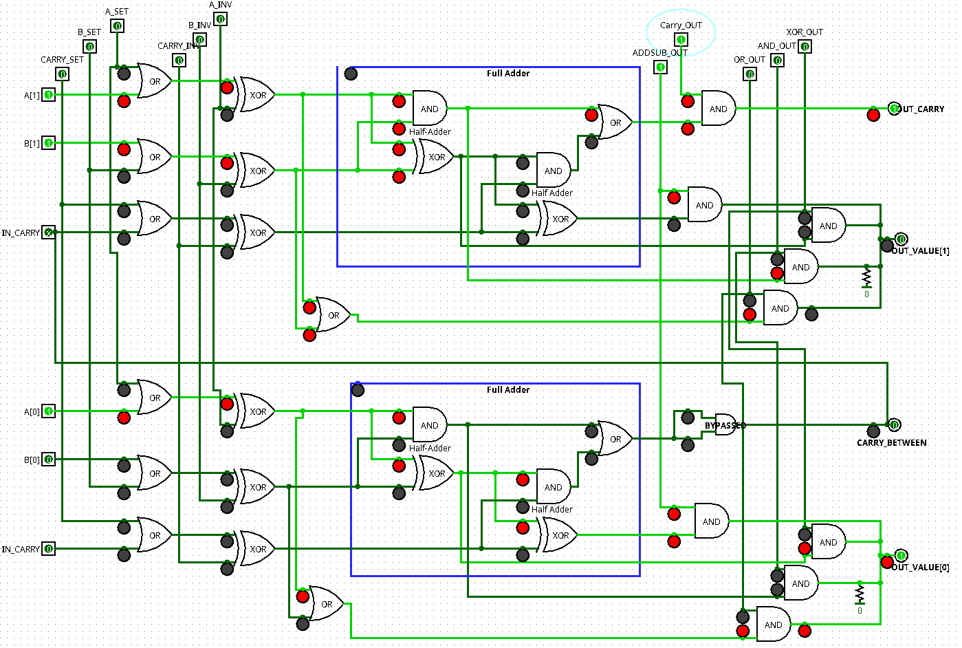
I’ve attached an expansion of this to 2 bits in Logisim format : alu_bit2.circ (30.7 KB)
Screenshot is doing an unsigned 11 + 10 (3+2) , and getting a result of [1] 01 (5, with the carry flag) with Logisim.
Original Logisim here (development stopped, but it works and it’s simple.) http://www.cburch.com/logisim/
Updated Logisim-Evolution (Open Source is great) https://github.com/reds-heig/logisim-evolution (The file should have worked in both, but evolution, to be able to do some nifty things like generate Verilog code, doesn’t allow duplicate labels, but importantly does allow zooming) So here’s a version expanded to 3-bits alu_bit3_evolution.circ (27.1 KB) Note that in either, you need to be in “Hand”/Simulation mode and not “Arrow”/Editing mode (on the toolbar)
I used these instead of Vivado, because Vivado will optimize things into LUTs which don’t explain things much, the simplicity of Logisim is good, but both versions are a little frustrating.
In the next part, We’ll finish up all the ALU operations that most computers do, and add a rotator, We’ll also, start to go a bit more into verilog to see how to build the ALU in a better way than just copy/pasting the modules, like our 5-bit adder above.