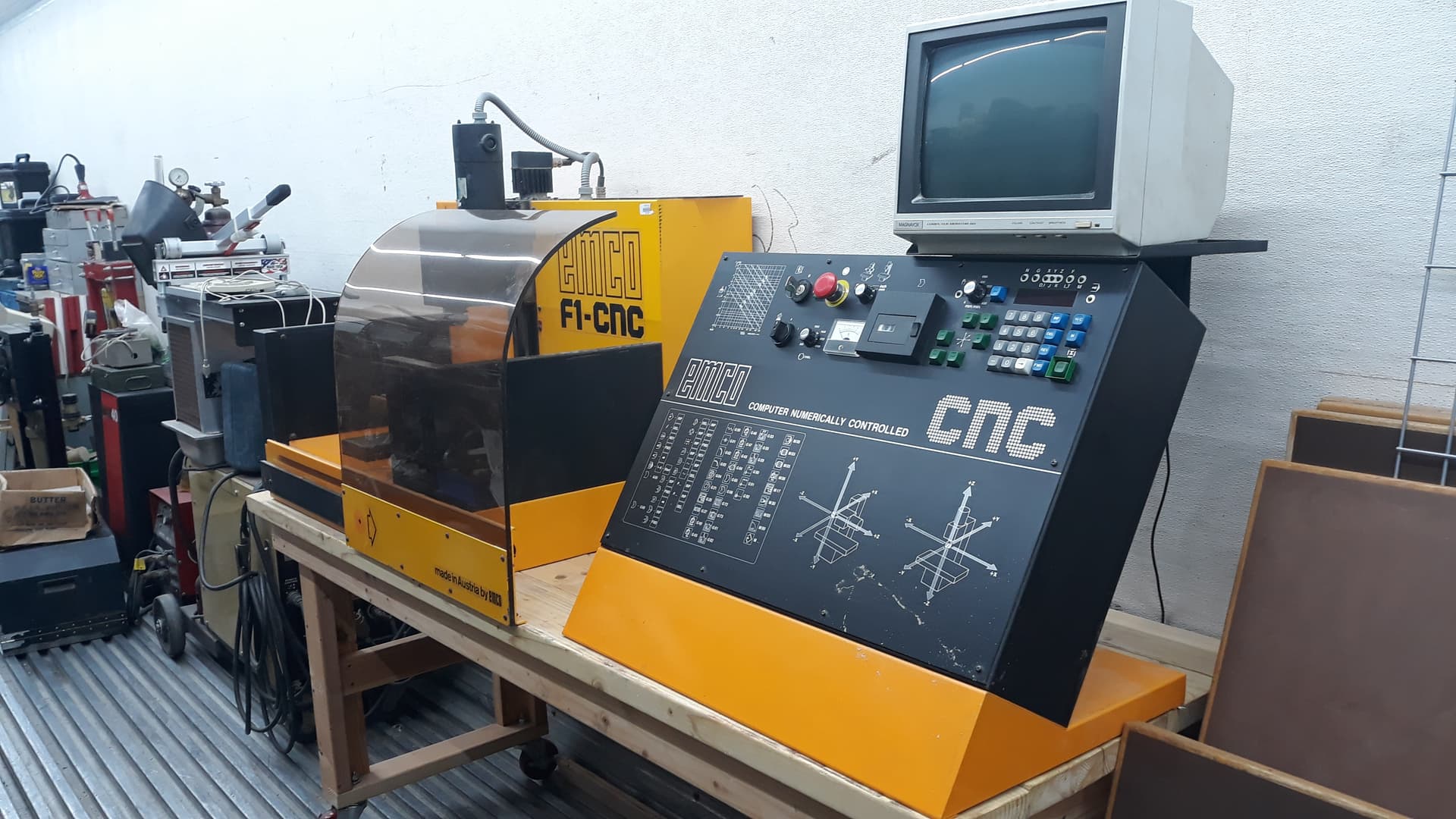
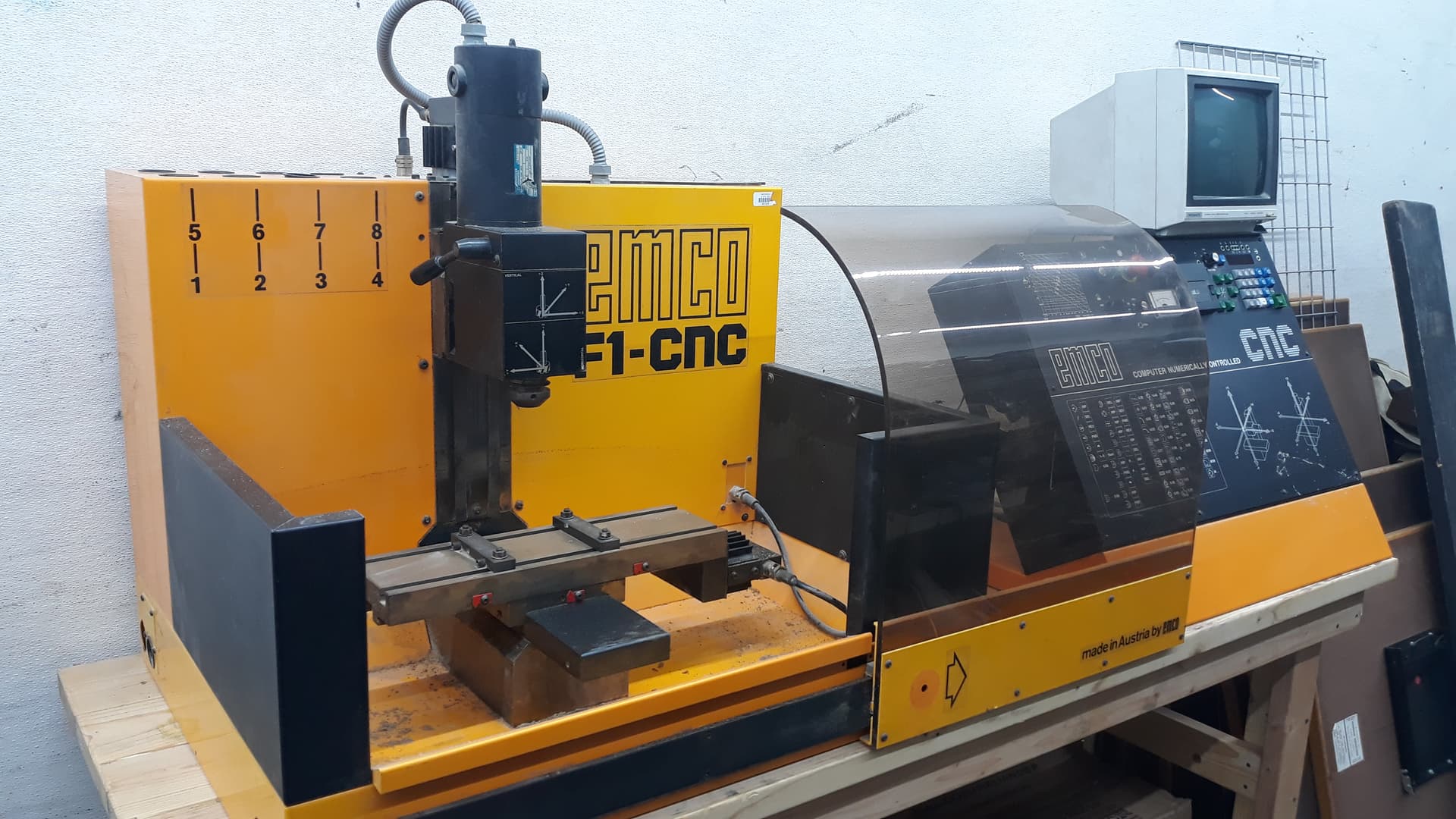
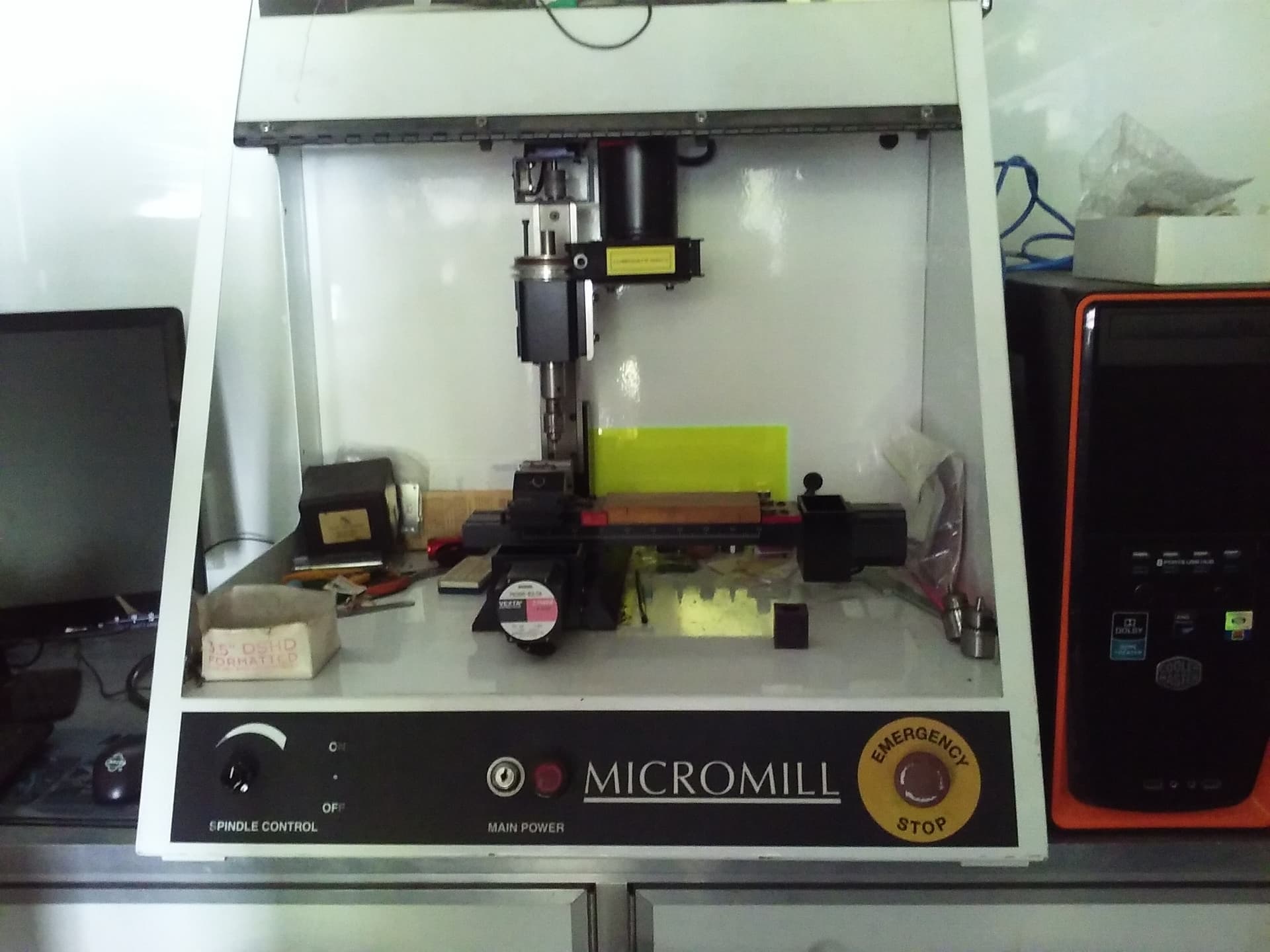
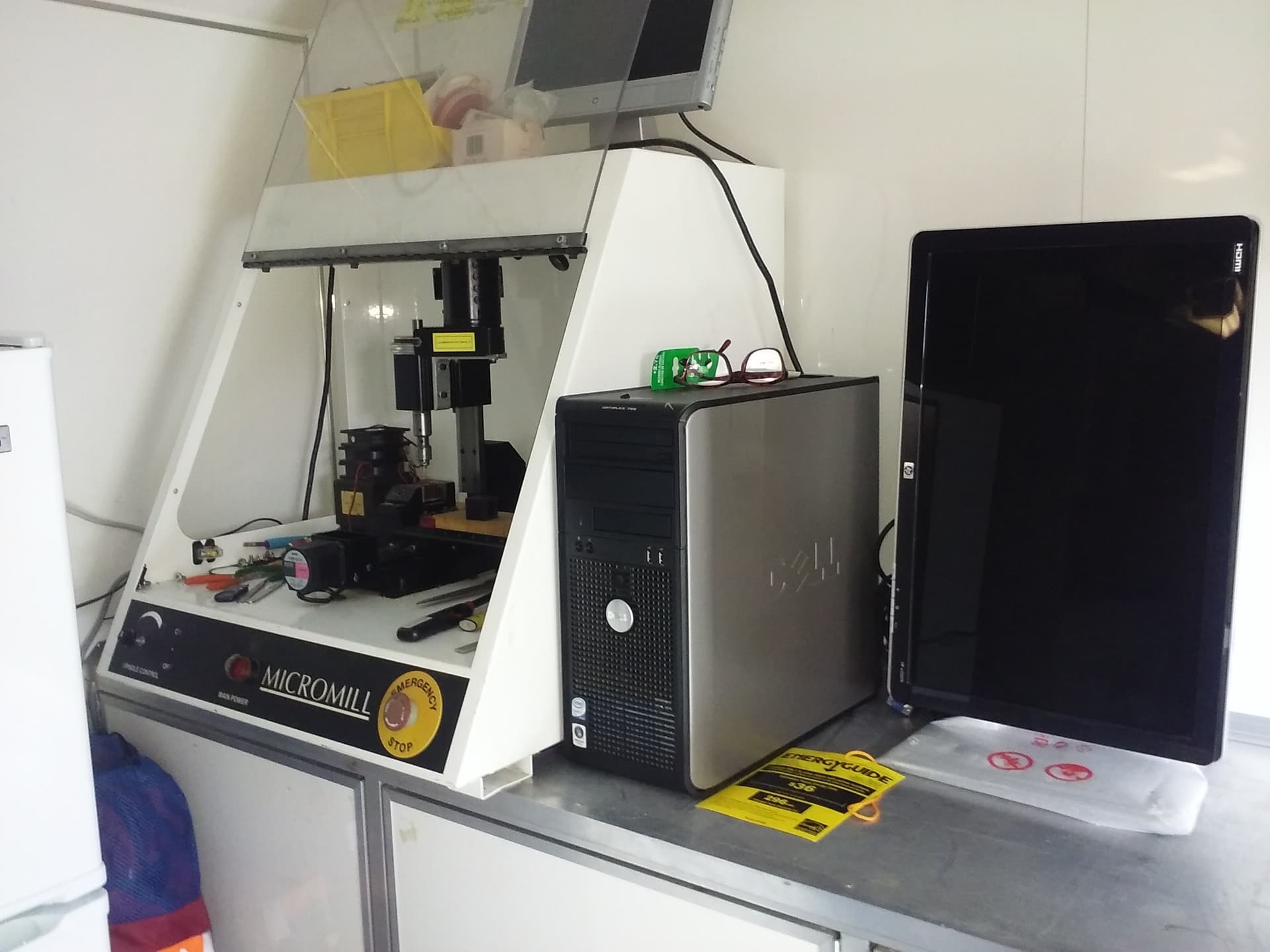
So, after a while of other people looking at it, and always having other things to do, I’ve finally got the computer, and lathe all together. I thought the control board as well.
The electrical interfaces are in a manual, linked here: Re: I have a emco pc 50 turn and a emco pc 50 mill There should be a copy of it with the lathe, but I can’t find it.
A couple of notes/questions I’d ask for background:
- Why not use GRBL?
-
- GRBL is great, and for most (slower) mills, I think it’s easier and arguably better at that task compared to LinuxCNC or Mach. It could do some of the lathe, unfortunately it lacks a very important feature: spindle syncronization. Which means it can’t work with the rotation of the spindle to do things like threading, which is a VERY useful thing on a lathe. LinuxCNC also has scripts for controlling the tool changer that other people have written. (Not that it would be hard to write for LinuxCNC, for GRBL it would probably be surprisingly annoying.)
- Why not replace the motor drivers with new ones?
-
- New motor drivers are generally significantly better, however, the machine as it is uses a 5 phase motor. It could be done, but as I think the only major problem is the lack of interface card, I think it should work and be significantly easier. (It use an old ISA card, which I can’t locate.) Fortunately, It interally use a step/dir interface. (Theoretically it uses RS485, but I haven’t been able to get any response, nor have I found the software.)
- Why not use a Pi?
-
- Pis for all their wonderful uses aren’t great at accurate timing/high speed. This is due to a few things. One of them is the graphics processor taking over the memory bus for variable bits of time, the other is that generally the timing isn’t super great, and on the Pi, you couldn’t for example dedicate one processor to IO and just time it. (You kinda can, but there are some issues like not being able to disable the interrupts on a single core, which is problematic.)
- Why not use a Beaglebone?
-
- The things can work, but seem incredibly fragile. I may have some toasted simply because a serial cable at 3.3V transmitted something after the power pin was disconnected.
- Pi Nano?
-
- It could work, but it would need to be written. (I’d love for a high speed interface between a nano and Pi, because that would be the solution to the above. I don’t really want to write it though.)
- So Why a parallel port?!
-
- Because parallel ports are one of the few GPIO locations on PC computers. There are some, that do have some, but they are rare. So older parallel ports with 8 Outs, 5 Ins, and 4 in/out ports at 2MHz tend to be both sufficient for CNC and some of the lowest latency generally available. (Yes it’s only about 2MB each way, but the time interval is known, higher speed things generally trade off latency for higher bandwidth.)
- USB?
-
- USB is great for a lot of things, but it’s relatively high latency Depending on version can have (minimum) latency of 1 ms (1/100th) of a second, or 0.125ms (125us 1/800) of a second latency. Which sounds tiny. Until compared to the antiquated parallel port at 0.0005ms (0.5 us 1/2000000 sec) For reference, LinuxCNC expects it’s two main threads to be operating at 1ms (servo) and 25us (base) +/- some jitter, which with 125 us rules out usb)
- FPGA?
-
- The gold standard for control. If you want super precise control you can’t beat FPGAs for accuracy and flexibility.
-
- Things like the Zynq & similar FPGA+ARM excel at things like this in theory since they run Linux on ARM cores and will in terms of using the FPGA IO run circles around just about anything for latency control. (The ones on the base Zynq-7010, each pin is theoretically capable of output at about 1,200 MHz, with 100 pins.) Unfortunately it appears the existing LinuxCNC FPGA code may have not been maintained.
-
- Others like the Mesa boards aren’t exactly cheap. (Though interestingly it appears they now have a Pi one.) https://store.mesanet.com/index.php?route=product/category&path=83_85
Also: KISS
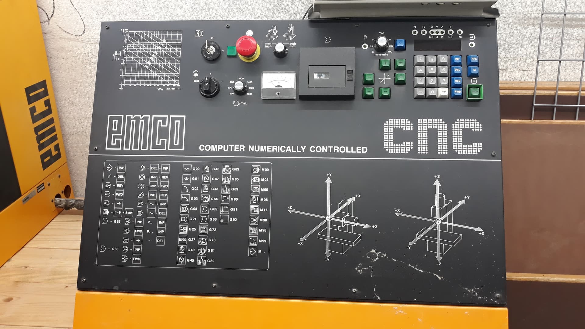
Note that for lathes, they use XZ, a little counter intuitively (at least to me) until you look at it from the perspective of the work piece. Z = height from chuck, X = distance from center (Y would be distance off center, generally not something you want in a lathe.)
Pins for control:
Spindle control:
Spindle DIR (OUT)
Spindle Enable (OUT)
Spindle PDM (like PWM, but with more switching, note in the documentation what would be called STEP is called CLK or CK) (OUT)
Spindle sync (2 IN, which may be SR/NI)
Z Axis Step (OUT)
Z Axis Dir (OUT)
X Axis Step (OUT)
X Axis Dir (OUT)
Estop (IN)
Master power cut (OUT)
Toolchanger (more later, may be subprocessed to an arduino) (1-2 IN and 1 OUT)
Which brings us to 9 OUT, 5 IN, (unless I forgot something) which will use 1 of the bidirectional pins as an output.
Spindle has two optical sensors one with a certain resolution (I took pictures so I’ll count) and a second which will serve as index.
If needed the toolchanger or other things not requiring realtime coordination can be offloaded to something like an Arduino.
@ssaner and I were able to with the wiring diagram and some tracing get many of those pins figured out, though it is a bit confusing since it’s under half English over half German (and substituting 120VAC for 230VAC everywhere) and my German is both very rusty and wasn’t that great to start with. I mentioned times and we’d mentioned next Wednesday at 6-7, if @saner is good with pushing that back, because there’s another meeting at that time?
This is also helpful, note that it’s for the mill version, not the lathe, but looks near identical electrically to understand the signals (and corrects one I got wrong.) emco pc mill 50 & similar - Page 15
We’ll need a new control board, the one I thought we had for it being good actually had stepper drivers built in, with no way to disable them. Ooops. So I’ll see about one that’s basically straight through.
Once we get it moving we’ll need to teach people all the wonderful things like tool offsets, and how to measure and set that sort of thing. (I plan to see about keeping many of the same tools in the machine normally, maybe 1 exterior, 1 interior tool left open/variable.)
TODO list:
Finish tracing wiring out, and confirm via multimeter.
Get straight through control board, or just directly hook into the cable.
Setup LinuxCNC via stepconf (pretty easy)
Fix the SMI (LinuxCNC Documentation Wiki: FixingSMIIssues which makes it go from bad to good in terms of latency)
Count number of holes on spindle interrupter disk.
Chips for single pin output to differential output (26ls31) and vice versa (26ls32) or (Ti’s SN65LVDS1, SN65LVDS2) or whatever. @james.a.seymour Thoughts on good chips for that?
Might be worth milling/drilling a quick PCB, rather than a premade one.
Any questions/thoughts? (Other than when will it be finished?!)