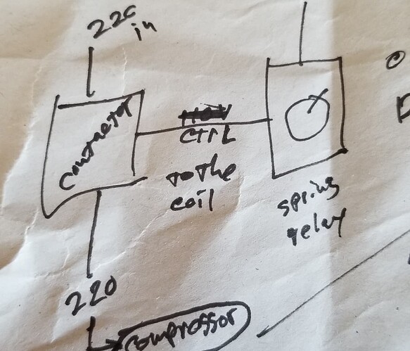
It sounds like we need to make a relay, and minimal current sensor to monitor and turn it on/off, for that and the woodshop. At that point, Why not add a card reader as it’s easy, as a check if they should be able to, since I know people have been complaining about not having that.
If we can get the high voltage side which can take an enable signal (Frankly, it should could probably just be a relay-transistor-optoisolator on one side) and a current sensor like: Non-Invasive Current Sensor - 30A - SEN-11005 - SparkFun Electronics (One of the few in stock) as a check it can be setup to:
Authorize someone and turn it on/off.
Check voltage
Report status via something like MQTT. (Very simple messaging protocol, often used for weather reporting, but it’s bidirectional so it could potentially allow for turning off remotely)
Temperature sensor also reporting via MQTT.
I’d base it off an ESP8266, as I’ve done most of that (minus the switching) before on that platform, so it’s simple enough. At this point, I’d make it monitoring only though.
Quick parts list (est prices in packs, not necc including shipping):
- Esp8266 mini D1 ($2-3)
- Sparkfun current sensor ($11)
- BMP280 or similar sensor (Also a pressure sensor, and reads a bit high depending on how often it’s checked.) ($2)
- Card reader ($2)
- Wire
- Relay ($20?)
- Optoisolators (Not 100% technically necessary, but a good idea)
- PCB (simple enough to make or order.)
- 5V or 3.3V power supply. (Can use USB power supply + micro USB as input)
If we want to get the current sensors & relays, I think I can make a few prototypes. From what I’ve got on hand.
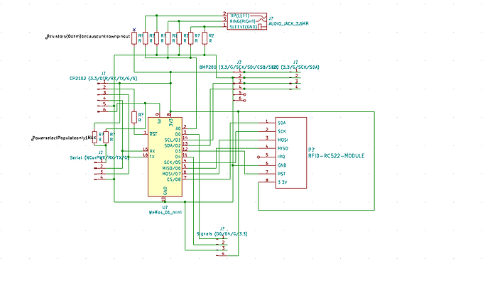
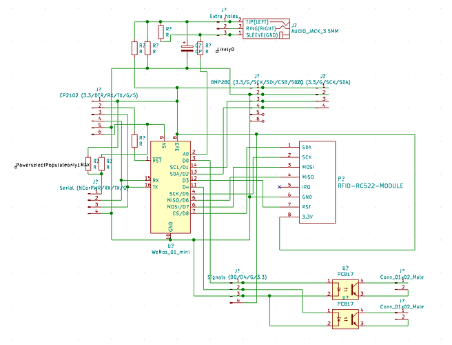
I’ve made a simple schematic,
Quick notes: Top ‘resistors’ are there only as switches/clamping/construction of a resistor divider, because the sensor’s documentation is iffy on which pins are which on the connector. I2C has another header in addition to the one for the temp sensor.
Left upper header is for a CP2102 debug, with reset (unpopulated by default) if needed, same with the lower header. Lower for a cable like this one: USB to TTL Serial Cable - Debug / Console Cable for Raspberry Pi : ID 954 : $9.95 : Adafruit Industries, Unique & fun DIY electronics and kits or serial communication to another device, (or just 2 IO pins & resistor switch power.)
D0 would be used as the signal activation signal. D4 is the onboard LED already, so it could be used later on as an LED. (Though due to boot modes one must be careful, might need a pull up resistor.)
I might add an optoisolator on the output header, but I haven’t found one I’ve got atm. (Which is mostly why it’s not laid out yet.)
If it works as planned, it could also be used to automate the dust collector to auto turn on, but we’ll see
Also, for the amusement: Going back I just found out the pinout via this project, but not the listed datasheet or other document that I saw… sometimes I love sparkfun documentation, sometimes I hate them, but it’s also almost what I’m looking at doing with the bmp280 even (Great minds or something): Environmental Monitoring with the Tessel 2 - learn.sparkfun.com I’ll go back later and now that I know, that should be much easier.
Eh, I just did it now.
@james.a.seymour and others: Thoughts?
