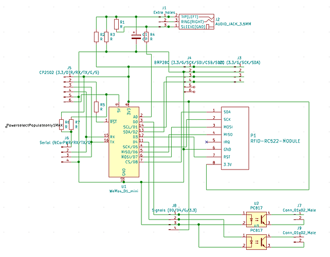
You raise a very good point about it. If it’s plugged in it’s fine. I’d thought about removing the 3.5mm plug and wiring it up directly. However, I think there’s a better version in that there’s the SCT-013-*** versions which aren’t 000 which are setup with a built in bias resistor for 1V per *** amps (going up to 100), in which case the SCT-013-030 Datasheet (PDF): https://www.arduino.cc/documents/datasheets/E000020_Non-invasiveAC%20currentSensor30A.pdf is more or less what we’d want (and could be swapped for others), and it eliminates the possibility of being unplugged or similar. And actually won’t change the circuit (though I’ve annotated it to be easier to refer to), The bias resistor (R1) from the other design is kept, either unpopulated or as a safety backup, with a relatively high value. (Even as low as 1k will alter it by about about 6%, 10k <1%. Since we more care about on/off, though power monitoring would be nice, that does require more, which couldn’t be fully done on this board. (Oh, look, is there serial to go to another board in the future? ![]() )
)
R2 = R3 = 10k (forming a voltage divider)
R4 = 0
@jeff Yes, that’s most of the point of the schematic. It’d not be a good idea to try and pull wires. This design uses a wifi connected part, so it can do the whole network thing, eliminating the need/want.
The SCT-013-030 seem in stock various places and with the SCT-013-*** series switching to another value 5, 10, 20, 30, 60, 100 A is just a software change, and IMO safer. Plus potentially monitoring power use.
