I’m currently working on the new badge reader design. I’ll be adding a reader to Luigi and replacing the current Raspberry Pi based reader on Mario. After that we’ll need to order some more parts so we can put one on the Tormach and a few other machines. Eventually we will adapt this design to replace the readers on the doors as well, but that version will need a bit more work and a wired ethernet connection.
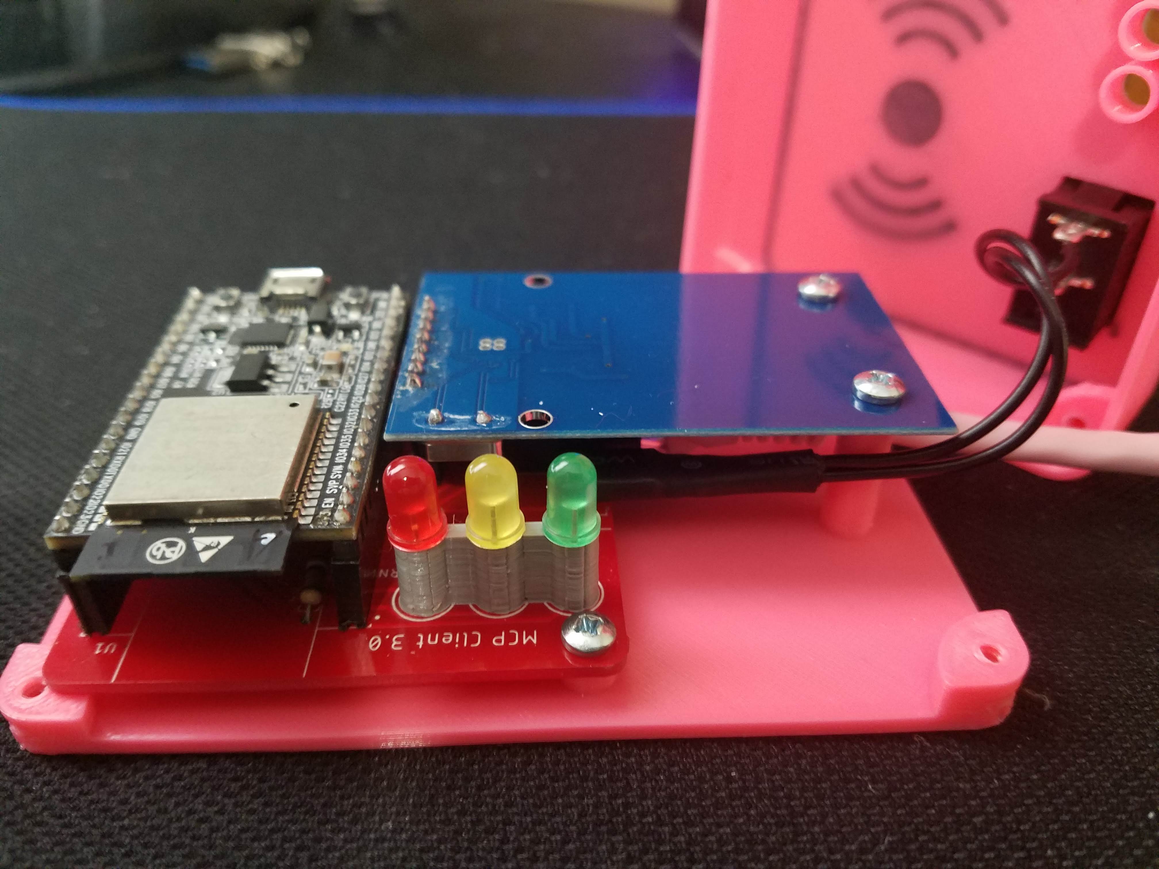
This new version uses an ESP32 as the controller. It has a few distinct advantages over the Raspberry Pi; less operating system overhead/complexity (runs FreeRTOS), no SD card to get corrupted, and faster boot times. The ESP32 is a pretty neat little microcontroller. It is the successor to the popular ESP8266. It has a dual core 32-bit processor that runs up to 240mhz and has built-in WiFi, Bluetooth, and a bunch of other stuff. You can get the module for about $4, or you can get a more user friendly development board (pictured below) for $10.
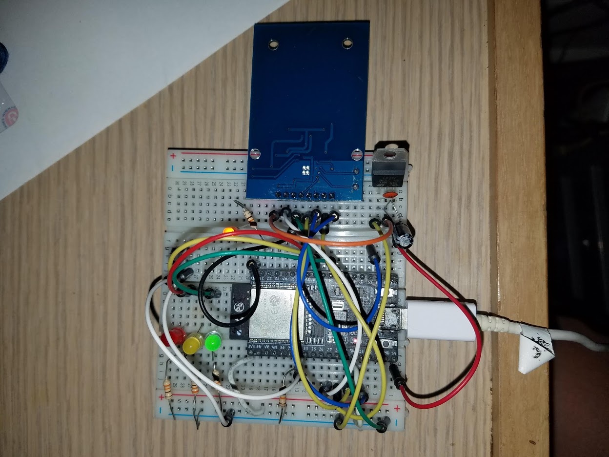
I’ve got the basic circuit and software working, but there are still a few things left to do before we can start attaching them to machines:
Fix a couple software bugs
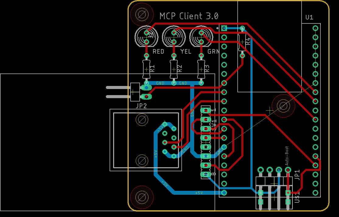
Finish the board layout in Eagle
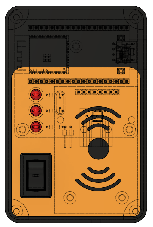
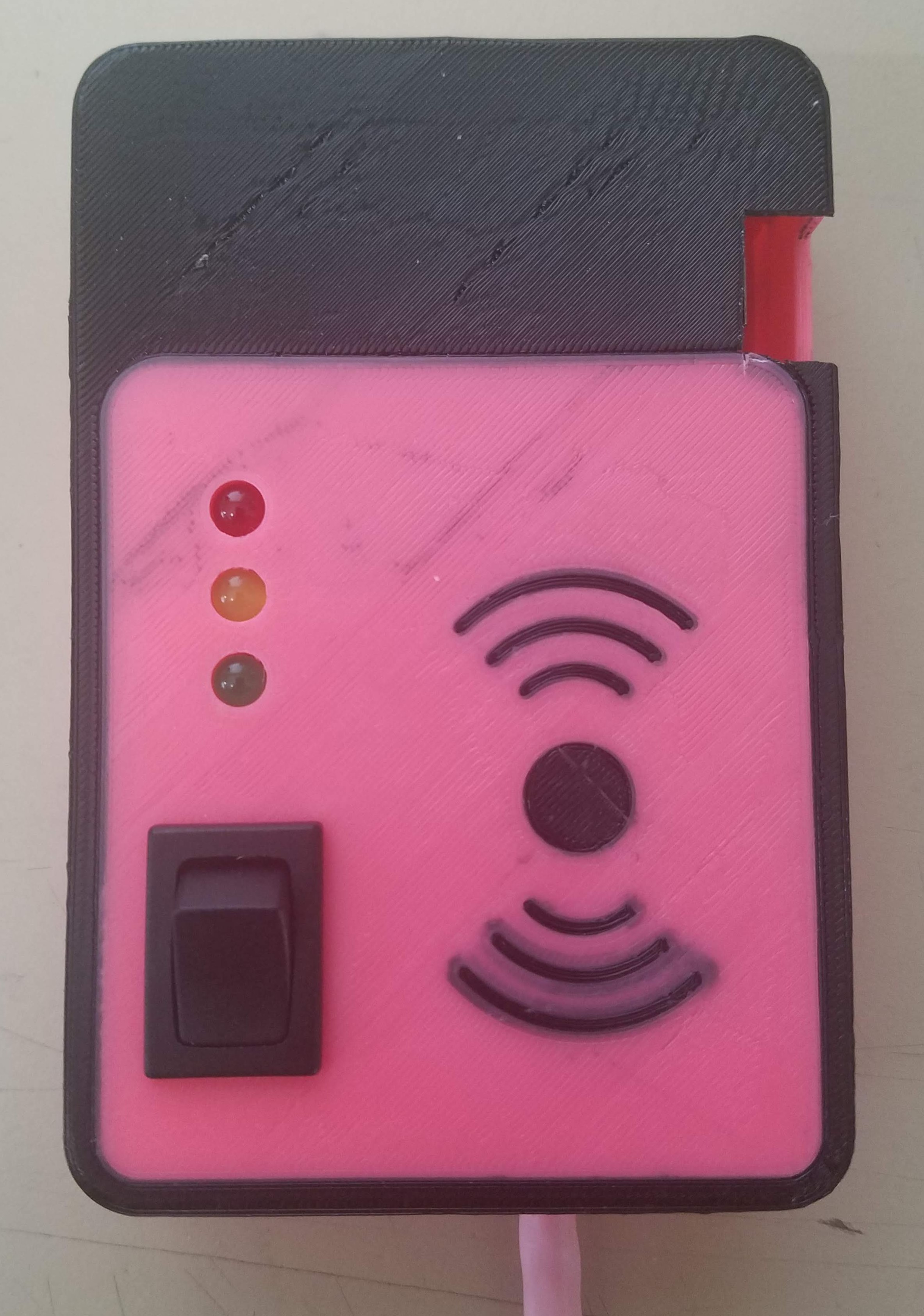
Design a 3D printed enclosure
I’m planning to start attending the project night on Tuesdays to work on this and other makerspace projects. If you want to check it out and learn about it (or maybe even help out ) feel free to stop by or send me a message.
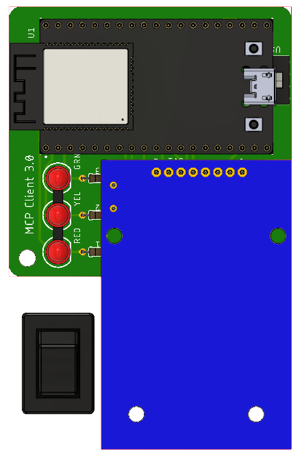
I’ve got the board laid out and the case designed. I used Eagle for the PCB layout, so I was able to use the Fusion 360 integration to create a 3D model of the board. I had to make some custom models for some components and import them into Eagle, and that part was pretty confusing and frustrating until I figured out how it works. The sync feature has some annoying quirks, but once I got everything set up it was pretty handy.
I’m planning to send the PCB design to a board house and order parts this weekend.
I got the boards and parts in last week and assembled one for testing. Everything seems to check out, though I’ll need to make some minor tweaks to the case design. Next up is building the power supply and relay module. I’m thinking about adding a current sensor on the AC input to detect if the machine is shut off separately via some means other than the card reader (another power switch, emergency stop, etc.) so that the reader doesn’t stay active with the machine off.
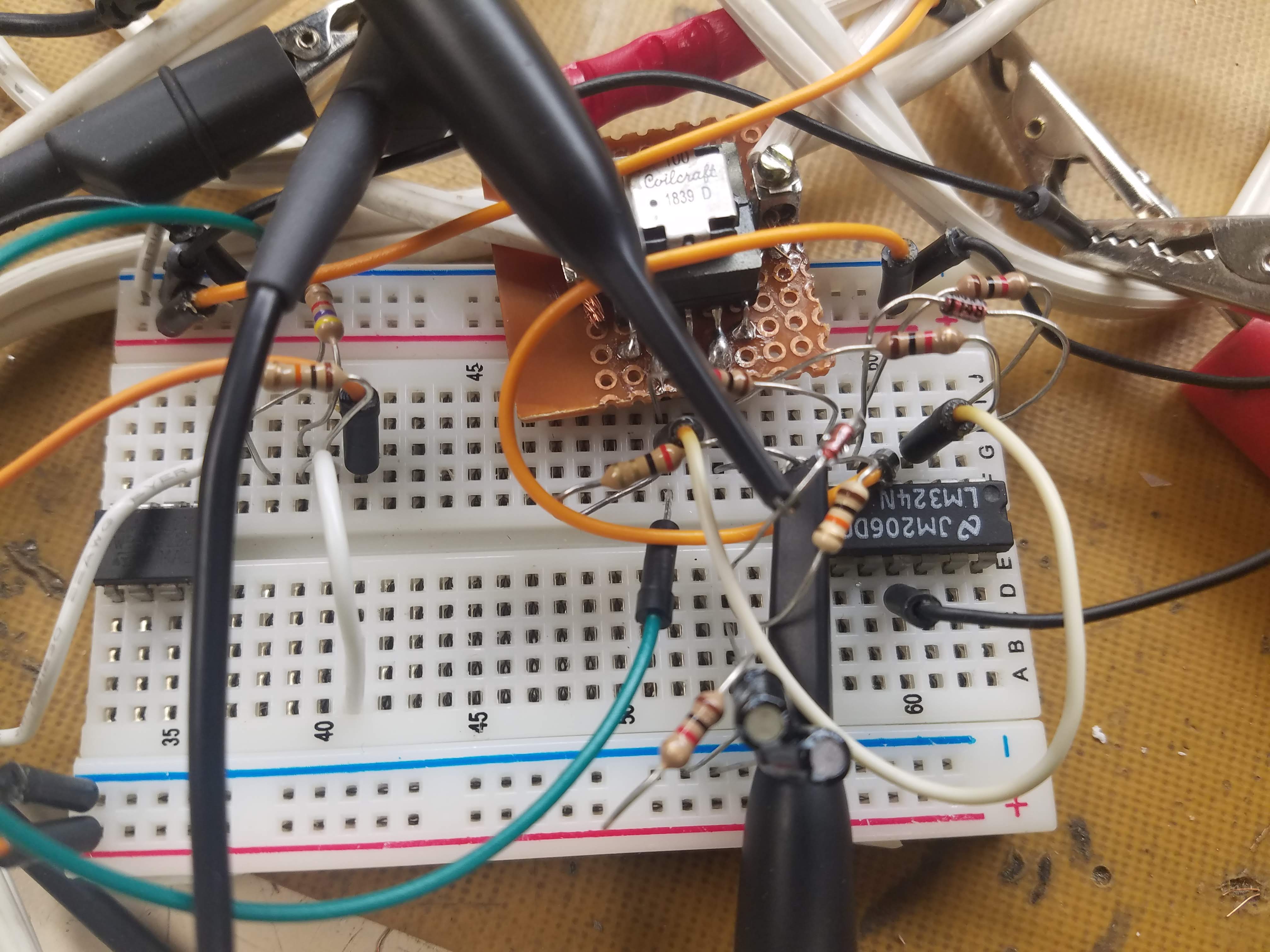
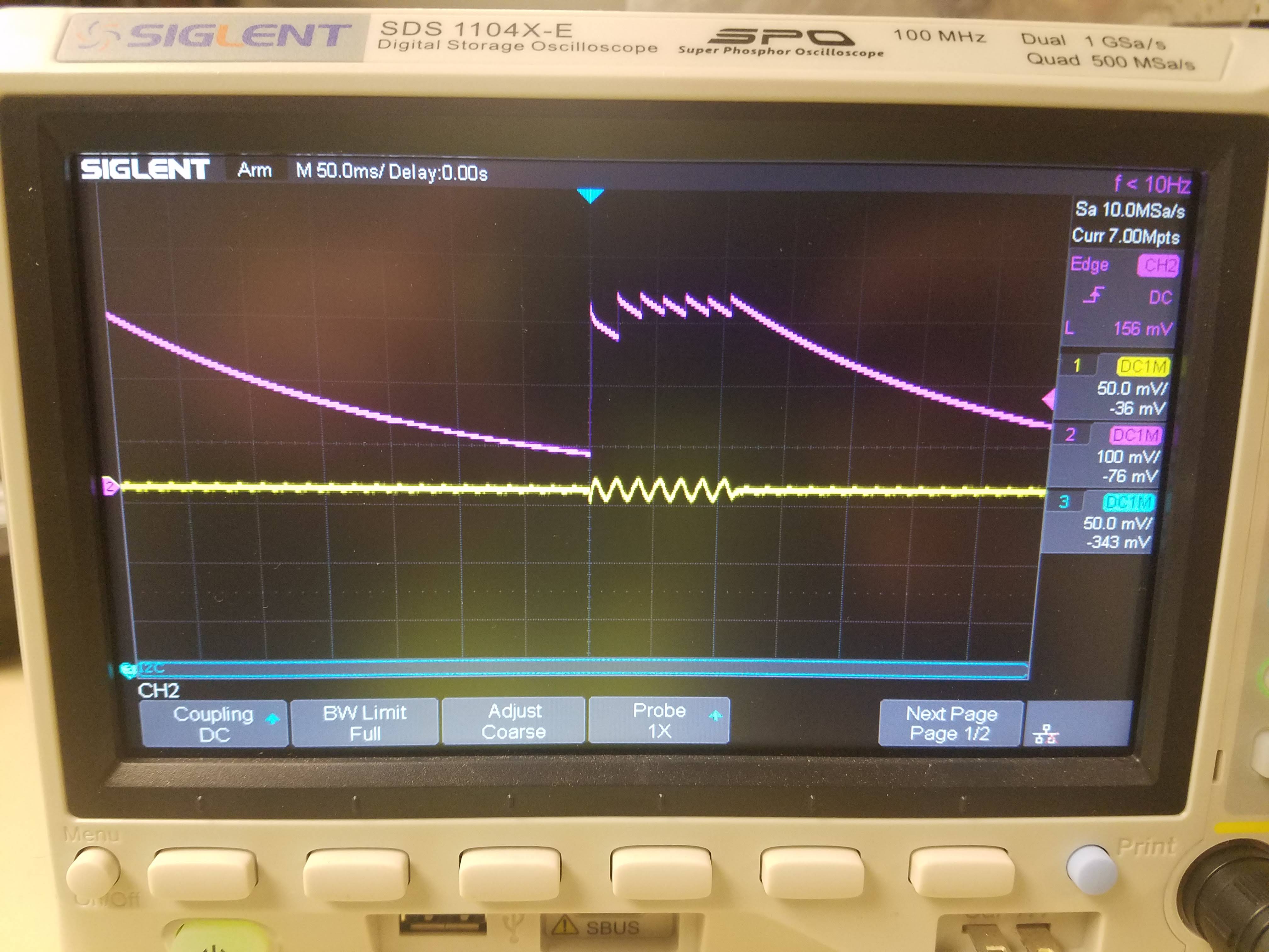
I’m making progress on the power and relay module. I got the current sensor working last night thanks to our handy-dandy oscilloscope. It uses a transformer to produce a small voltage that is proportional to the current through the AC lines. This small AC voltage is rectified and amplified using a precision rectifier circuit and read by an analog input on the esp32.
Thanks, it’s getting there. Just finished the first draft of the board layout for the relay module. Trace widths are ridiculous to support 20 amps in 1 oz copper.
If this is for the makerspace, they should be defraying your costs. EDIT: I guess I already said something like that on this thread. That means that the drugs are either really bad or really good.
Got the rest of the parts ordered yesterday. Should have everything in by this weekend. All that’s left now is to design and print the case for the power and relay module and update the code to support the new current sensor.
I got the rest of the parts in yesterday and assembled the relay board. I did have to make a minor modification to the reader board because I found out that ADC2 (one of the analog to digital converters on the ESP32) is not usable when the WiFi is enabled. Whoops. So I cut the trace and added a jumper to a pin connected to ADC1 and everything is working.
I tested with a PC fan that only draws 40ma and it had no problem detecting when it turned on and off, so I think it should work for any equipment we want to attach it to. I’m considering removing the toggle switch on the reader and just using the current sensor in conjunction with the existing power switches on the machine to toggle the reader off when the machine is no longer in use.
Just need to finish designing and printing the case and it will be ready to install.
 ) feel free to stop by or send me a message.