Heh, I’d forgotten this as a draft on the web forums for a while.
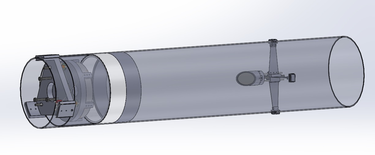
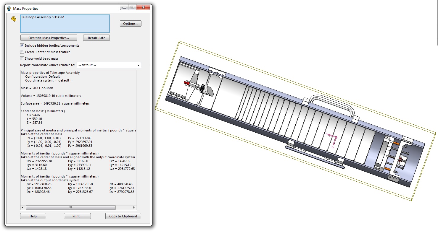
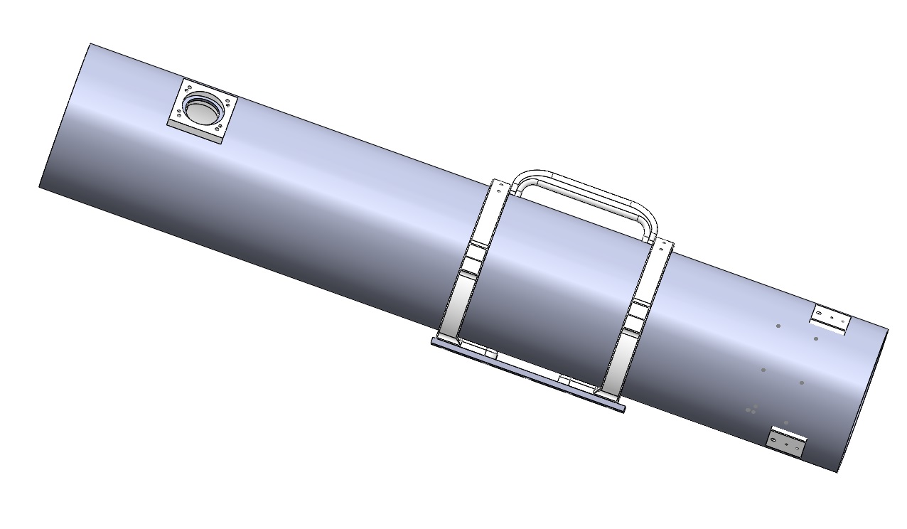
So I figured that since I can’t do much with regards to things physically. (Yes, I’m worried about Covid.) So, I’d post a bit about one of my projects, which is a telescope control setup also some pretty pictures.
Here, have some pretty pictures first, before some theory and more pretty pictures.
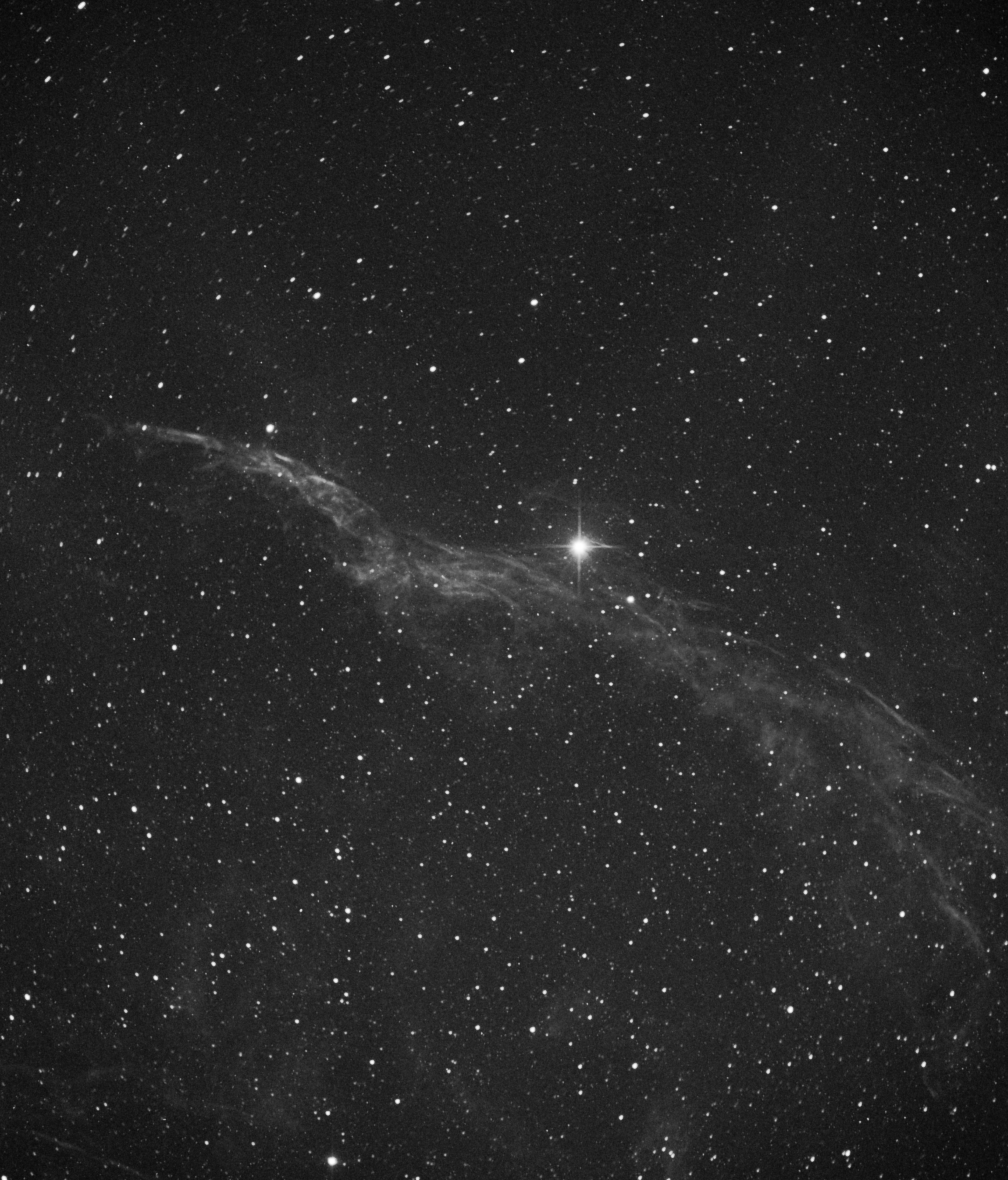
Eastern Veil Nebula
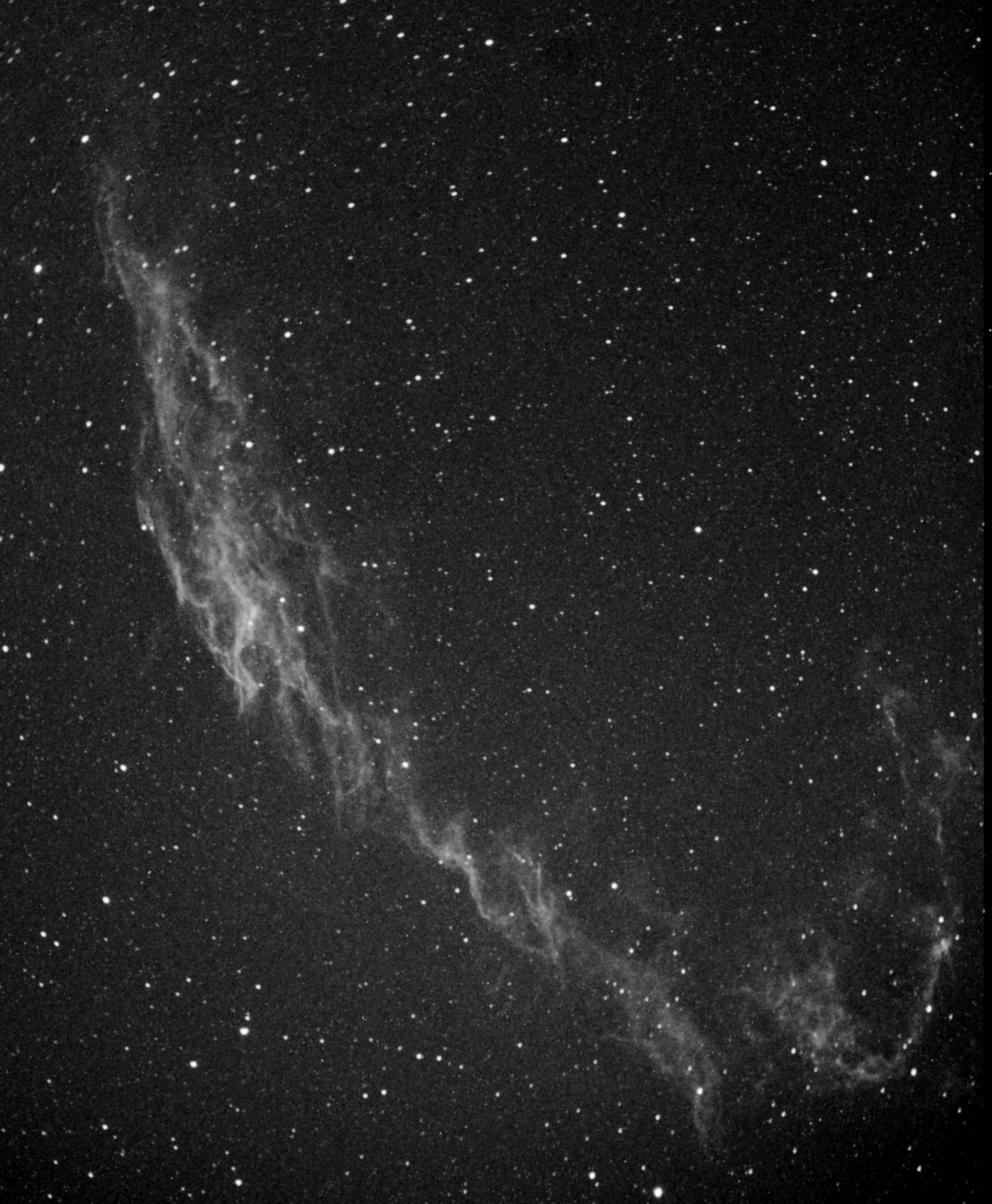
Western Veil Nebula
So a little theory first, with regards to coordinate systems. You can point to anything in the sky using two axis, Altitude (angle up in the sky) and Azimuth (angle away from north, If it helps you can call this bearing.) However, things in your view will rotate, which isn’t an issue for visual observation of a target, but it is for any photographic observation. You either need to account for this via a ‘de-rotator’ motor, or take short photos.
However, there’s a system, called an Equatorial coordinate system, which instead of having the telescope’s movement axis tangent to the Earth’s surface, you align them with the rotation of the earth, then you simply have to move the one axis counter to the rotation of the earth, and boom, all the stars stay stationary with regard to your telescope! Add a second axis to allow for pointing anywhere, and you’ve got the ability to go anywhere in the sky. Then if you map things to that coordinate system, you can locate everything in the sky with two coordinates that don’t change for anyone on the planet. (Under ideal conditions/perfect alignment anyway.)
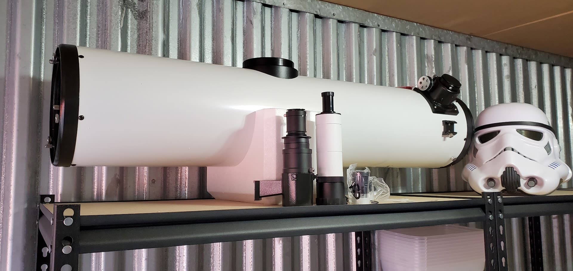
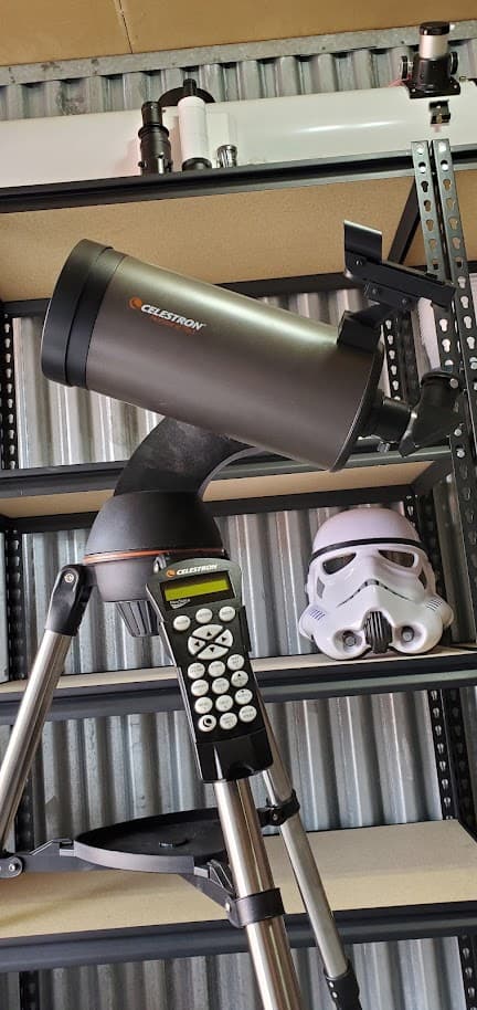
That’s why you’ll see most telescopes seeming be at an angle. That angle is easy to determine, it’s your latitude. (At the exact poles, an Alt-Az and Eq scope are the same.)
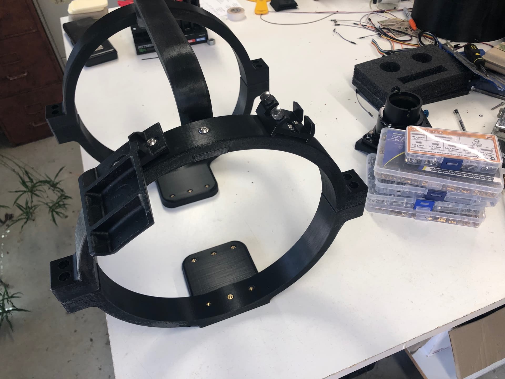
So that little bit of theory out of the way. I have added onto mounts, or made parts to allow a control system called OnStep to some telescope mounts. OnStep is open source, and runs on an Arduino Mega + Ramps on the low end and on a Teensy 4.0 (if you haven’t seen that, you might check it out.) on the high end. Mid rate is an STM32F103 which can be one of the smaller ‘blue pill’ (primary) or ‘black pill’ (names reflect the PCB color and they are slightly different, there’s a ‘red pill’ as well, blue has the most pins available) and a slightly more powerful STMF32, which is on a 3D printer controller as well.
There’s a system for Linux/Mac called INDI which is a network aware telescope control software (There’s ASCOM for Windows). I helped make the driver OnStep/INDI, which built upon existing. So now any Linux computer, like a Pi can be used. (I use a ECS Liva mini PC running Kubuntu, because I had it, though for anyone who wants to build their own, I’d highly recommend a Pi 4. More ram is better, but my device runs on 2GB, so not strictly necessary.) Which talks to the mount (OnStep) as well as the DSLR and guide camera, and to my laptop via gigabit ethernet. (You can also use VNC/RDP or similar to do everything on the computer at the mount, but I find that can crash (usually lack of memory), and if you sleep while things are taking pictures, you might wake up grumpy at that.)
When I draw it out (on paper if someone wants to see it), it seems rather complicated, but really is pretty simple. (Or at least as simple as a 3D printer or CNC machine…)
Anyway if people have questions, let me know. I’ll see about adding to this.