I’m using SolidWorks to model and would like to continue to do so but I’ve run in to the same snag with it that turned me off of using the ShopBot a year ago when I was learning Fusion. The post processor seems to be creating a toolpath that doesn’t appear in the CAM software. It starts 8 or so inches away from the pocket and is slightly below the stock surface. It seemingly has nothing to do with my origin point or coordinate system.
For me it seems to be unavoidable when making a rough cut. I have been practically beating my head against a rock trying to troubleshoot why it’s happening. I’ve watched endless YouTube videos, done Internet searches, and even talked to AI for far longer than I care to while exhausting countless possibilities.
Does anyone have any recommendations for a SW post processor that is tried and true? If not, do you have any general recommendations? If not, would anyone who has lots of experience with our machine be willing to take a look at the problem with me?
I have considered falling back to easel but there is a part of my project that will eventually need something more detailed than a simple pocket and I really just need to figure out what the issue is with the more advanced apps and LinuxCNC
Thanks for reading lol
Other than sometimes fighting with fusion to give me the toolpath I expect, I’ve not had trouble getting it to make the part. Maybe some pics of what you are seeing would help. I don’t know why either cam would create a toolpath not on the part. That doesn’t make sense. And the fact that you have the same problem on multiple platforms tells me it’s not the platform.
Thank you for responding.
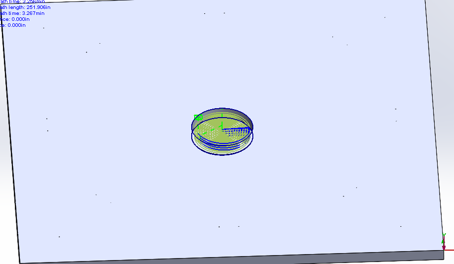
This first picture is of the toolpath. The project is literally an 18" x 18" piece of 1/2" 5-ply birch with a 2.6" hole in the center. There was another “drill” operation right before this one where I used a v-bit to spot .050 depth holes at various places around the face of the material but it’s suppressed.
I don’t think an artifact from the drill job is causing this because I recreated the whole project once without the drill op sketch at all and the jog still happens.
SolidWorks does not come with a LinuxCNC specific post processor but I tried the one AI liked best and it will only output a .nc file which Axis won’t read. So, I downloaded a post processor from this forum and installed it in SolidWorks.
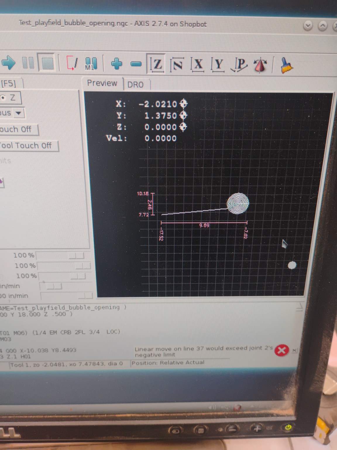
When I upload the final post process file to Axis: I get this:
The FCS is in the bottom right of this display.
These photos are from my phone storage. I can get more specific ones if requested. If I highlight line 10 in Axis the start point way out at the left turns blue. If I highlight line 11, the jog highlights. The vertical line is where the tool rises from the cut at the end. Making those lines into notes doesn’t get the jog to go away it seems.
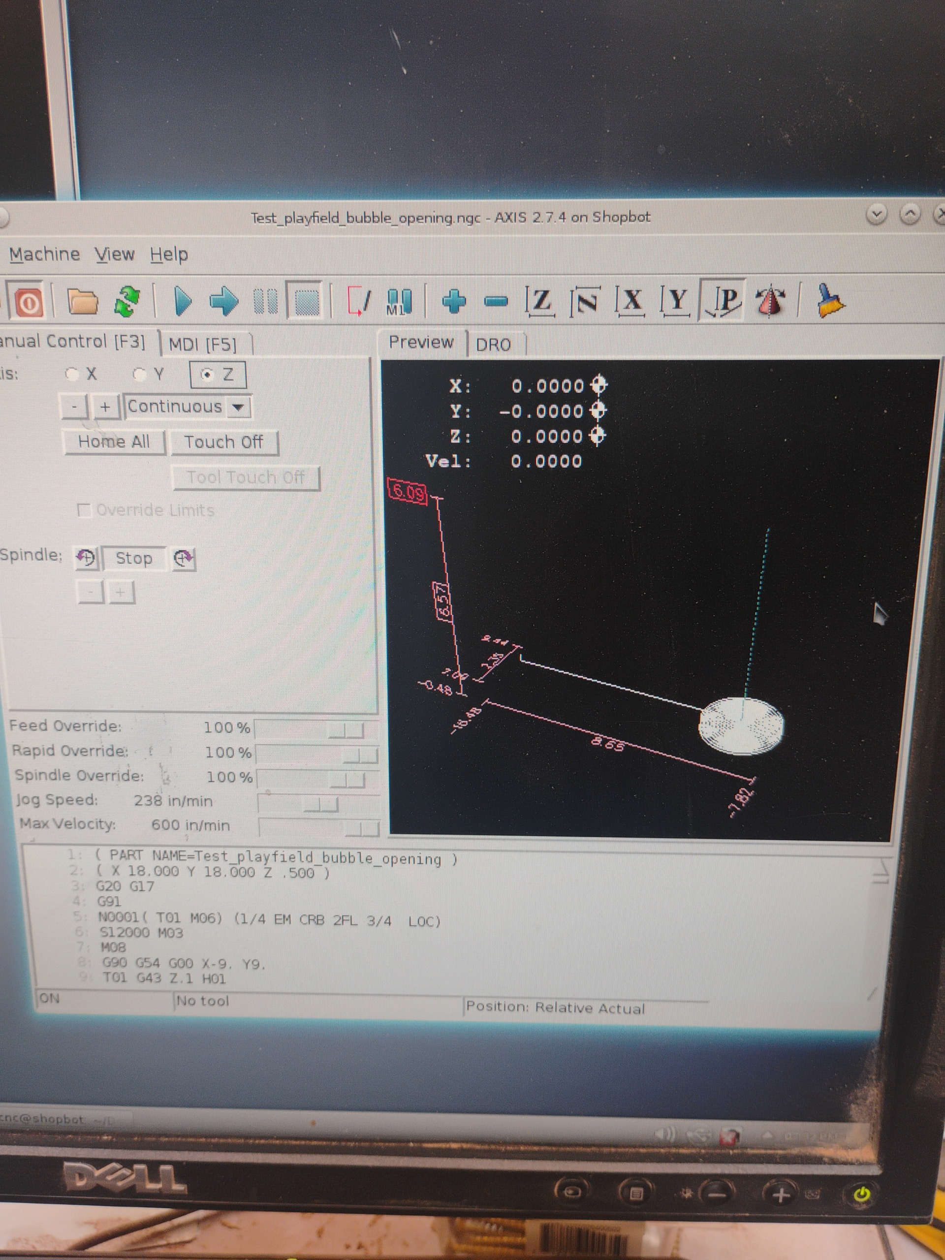
You’re talking about the straight line leading from the edge to the center of the spiral? Looks like a rapid feed from the start position to the beginning of the cut. Since your stock is 18" a 9" jog to the center makes sense. It’s a rapid feed so shouldn’t be cutting the material. If the tool path is below the surface of your stock you may need to look at your safe z heights for travel and make sure you are touching off correctly.
Should be this line: G90 G54 G00 X-9. Y9.
What is the height of the top of the work? You mentioned 1/2" plywood. Your toolpath shows a travel of -0.48". Can you confirm that matches the thickness of the plywood? If so, you may want to plan to go another 1/32" (~0.030) past the bottom to ensure you get a clean cut all the way through the material. If the bottom of the work is at 0, please fix this so you are not cutting a 1/2" deep pocket into the spoilboard, which somebody else has already done with a remarkably similar operation.
Problem solved! SolidWorks put a g43 and the program. Fusion 360 does the same and it always causes problems. Removing the g43 from the program made everything work like it should!
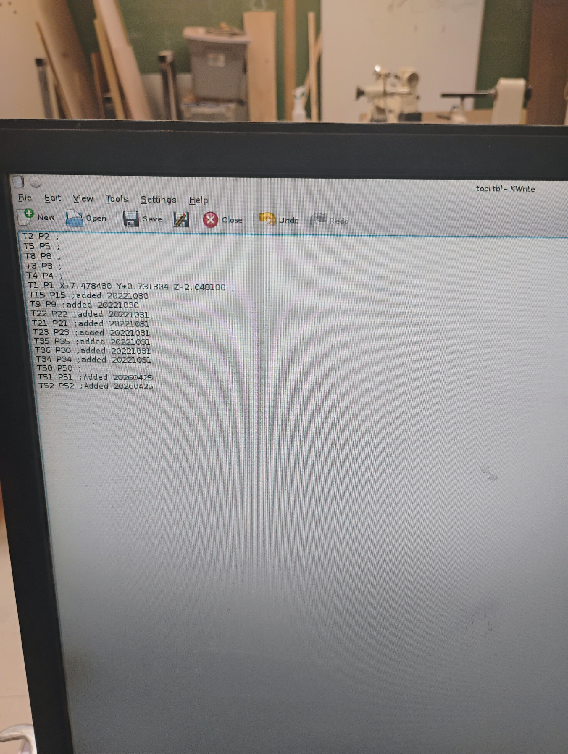
After you left I was trying to make sense of it and AI was talking about a tool.tbl file and I remembered seeing it when I was desperate once. Look what I found! Check out that T1 definition 6 lines down! Look at the X offset!!! Is that the real culprit?
My g-code that’s screwing up is:
T01 G43 Z.1 H01
In my tool crib the wonky cuts are made with tool 1, the cuts that were fine are made with tool 5.
Final update: I removed those numbers and it eliminated the need to remove G43 from my G-code.
For future reference:
When a modeling program like SolidWorks or Fusion outputs G-code, if you have multiple milling operations with different tool bits in your CAM, it will insert code that displays a dialog box during milling that prompts tool changes
I would like to utilize this feature for complex projects.
If you tell a modeling program that one tool has a different protrusion length from the mill holder than another it DOES NOT build those differences into the G-code. You have to enter them manually into a file called tool.tbl.
File manager>linuxcnc>configs>Shopbot>tool.tbl
The kicker is that if you insert the tool for operation one at the start of your entire project and touch off with it, the difference between the protrusion of tool one and tool two is what needs to be entered as the Z offset value for tool two. Tool one does not get an offset value at all.
Let me give an example: Tool One will have a protrusion of 1" from the bottom of the collet to the tip of the tool bit and will be used for operation one which is a Rough Mill. Tool Two will have a protrusion of 1.5" from the bottom of the collet to the tip of the tool bit and will be used for operation two which is a Contour Mill. Tool One is inserted into the collet and attached to the router before starting any operation. After homing and touching off the X and Y axis, You lower the tip of the bit to the surface of your stock and touch off the Z axis by using the paper method demonstrated in the authorization classes. One inch is now the baseline for offsets in tool.tbl for every other tool that gets used. The text in tool.tbl should look something like this:
T1 P1 ;
T2 P2 Z+0.500000 ;
When prompted by the program to change to tool 2, now the program will accurately cut your stock to the depths you specified in your CAM design.
I suppose you could touch off with just the mill holder or collet at the very beginning with no bit inserted at all to eliminate the need for calculating offset values at all…
In that case the text in tool.tbl would look like this:
T1 P1 Z+1.000000 ;
T2 P2 Z+1.500000 ;
I suppose there are trade offs for each method.