Microscope upgrade

Microscope upgrade.

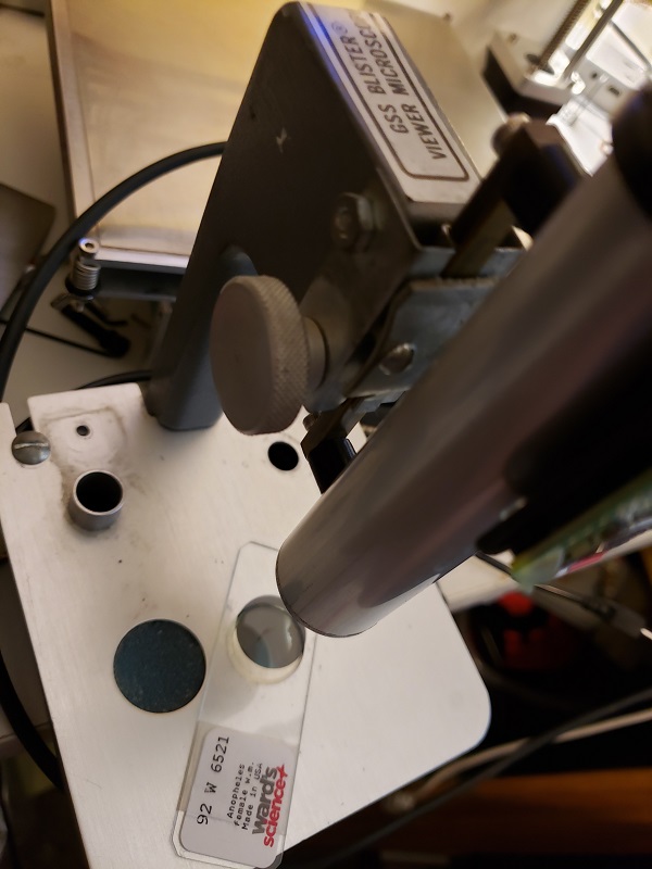
It is a microscope. The optics did not change. I did clean them. They were very dirty, and there was bolt missing and a nut rattling around in the tube. It has been upgraded. I would put it at version 0.9.

I took this up because I saw Daryl Goad’s hacking challenge note. I had more thoughts on making it way better, but that will take some time.

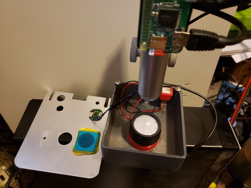
I connected a raspberry pi zero (so slow), but it can be hooked up to a tv. I have more software changes to make. It has been been converted from 110v to 5v. The leds should be cooler than the bulb, but I have not checked the original wattage of the bulb,but it has wifi now.

Before, I did not do a very good job of getting tons of original pictures.

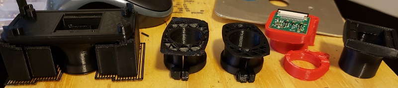
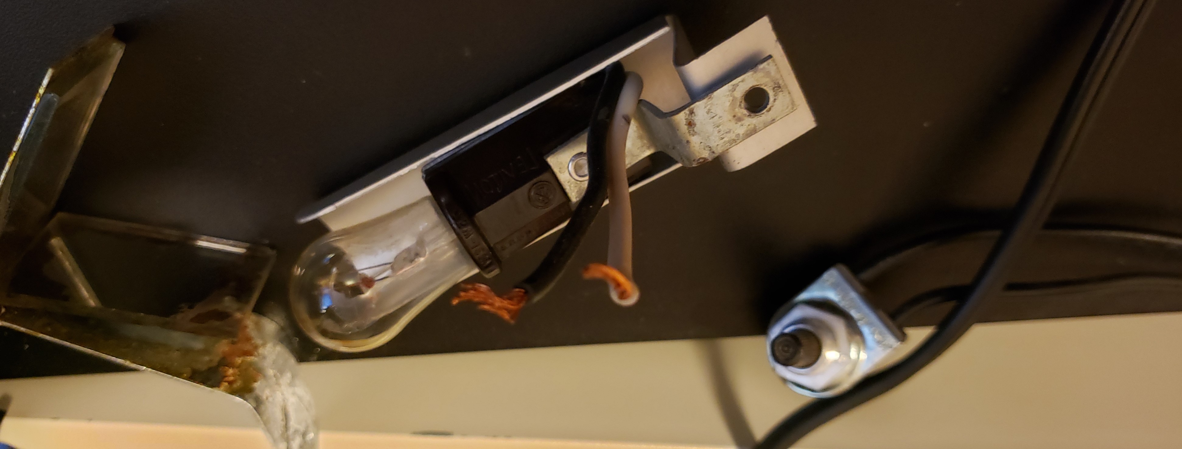
Here are the old parts that were stripped out.

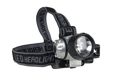
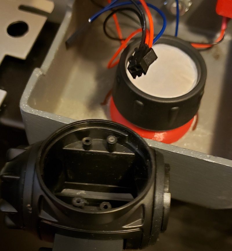
New stuff. The LEDs came from something like this, but it is a black body. They are overkill and I have some rgb leds coming but they did not show up in yet.
image

I reused the lense cover to hold the wax paper (diffuser). I had to model up the grooves /screw posts and 3d print.

With the guts open.

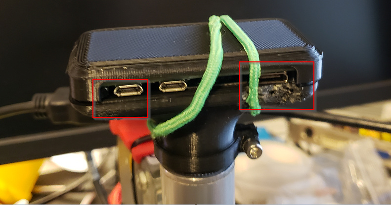
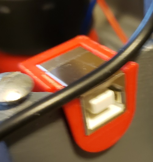
For power I reused an opening in the back. I printed a gromet to encase the usb (printer type connector) I found out that all of my super glue had gone bad, but it will come up if pulled very hard.

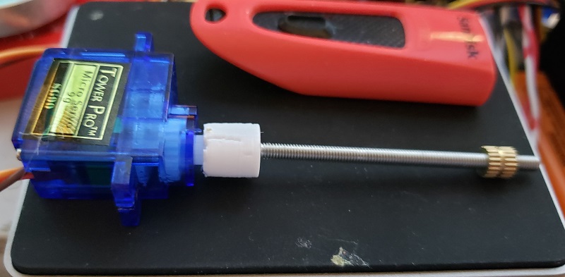
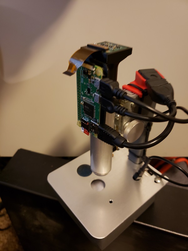
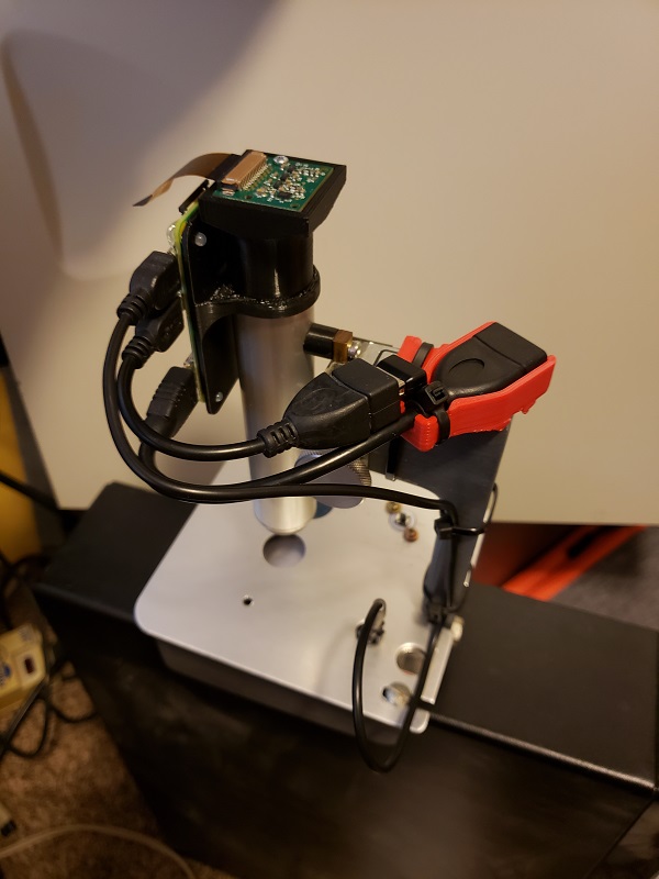
I had to design/print the raspberry pi lens mount to fit the eyepiece barrel, but it needs rework. Too loose and no fine adjustments.

The raspberry pi backplate slips over the eyepiece and hangs. It need to have a cover made, and made stiffer.

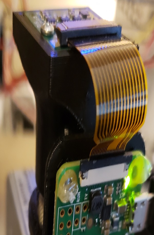
You can make out the custom red hdmi strain reliefe bracket. It is zipped tied to the post. This should allow easy attachment to different monitors/tv without trashing the connectors on the Pi. The longer ribbon cables I have do not fit the Zero.

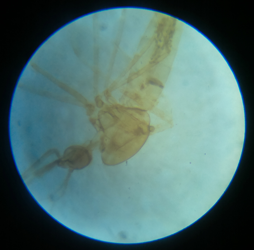
After I rework the top mount and get some decent pictures I will post them. I am also need to finish a scripts/program to stitch multiple pictures into a high res version.

The Pi zero is very slow. It is nearly impossible to adjust it and not go crazy with so much lag. Before I release it to kids and stuff at the space. I need to replace the zero with a full fledged pi, or just stream pics and have software on a laptop process things. I might possibly write an android app on a tablet if I can get it talking directly to the Zero for pictures.

Daryl if you are watching I hope you like it.

It was a nice Saturday project, and was fun to take up a challenge.

7 Likes

Sorry, no useful pics yet, but I made progress after a few failures. From right to left.
version 1. Too lose, can would not grip the tube.
version 2. (red) fine, but stuck to the tube so well that I had to cut it off.
verison 3. two failed prints… no support, no brim. Then 10mm brim. then full support, and it still had problems with the overhang printing. The support material was very hard to remove.

After waiting for yet another print, and finding out I did not give enough clearance on the lower print… I had to hack away with a pair of wire cutters.

Please don’t judge me on the hair tie/rubber band. I wanted to makes sure things fit before I added clips or screws.

Maybe I will have pictures tomorrow.

1 Like

First light.

3 Likes

I have the software for the RGB led (neopixle/ws2818) working, and the servos are working.

Converted to continious rotation. Just removed nubs off of the gears and diconnected the shaft from the internal pot. I have some linkage and alignment issues on the leadscrew, but I may just superglue the connector i made on when it is assembled and aligned. The m3 screw has a small pitch, so it will take a bit to move around, but for he microscope it should be fine.

ok, the next step is an automated xy stage. Here is the inital cad design.

Here is the test run of the slide. Mostly failures. I should have looked up the thread pitch on the M3 screw. It has such a high pitch 85ish TPI it will take so long to move the slide. I am going to have to swap out for something with a lower thread count. I could try a wood screw… that should fly, but I don’t know how I would attach it.

I have found working on the small scale is a total pain.

The shaft connector from the screw to the servo is just not quite concentric. I might reprint one and go for a press fit instead of hot pressing the head in. I wanted to use the screw on the end of the servo shaft to keep it from pulling off easily.

servo_screw
I think some of the problems are becuase I am using petg. I have not done much printing with it, and I was trying to make a small recess without support, so it is a bit rough where the screw should e seating in a recess.

I removed the sound because the servo is so loud. I will dig though the hackables to see if I can find some tiny steppers. Everyting I have would dwarf the microscope base. I had the micro servo so I thought I would give it a try.

The first two test prints worked out for the most part. The fit was too right, so I had to sand down some parts.

After fiddling with it I got the right amount of play, so it should work.
https://talk.makeict.org/uploads/default/original/2X/4/4975d86eec3d8255c597094968e9ef37c9859e71.mp4

1 Like

Better. It moves in a reasonable time frame. Still noisy, but not much that can be done with a $1-2 servo.

FYI, creating a video under 4mb. Is a pain

2 Likes