So, the probe on Mario keeps getting melted. This is not ideal. I would like to get one made out of aluminum to (hopefully) eliminate this issue. I’ve been meaning to do this for a while but haven’t had the time yet. It’s probably a pretty easy manual lathe project. I’ve attached a PDF with dimensions. The hole spacing for the 2 mounting rods is the most important dimension, the rest have a good amount of wiggle room. I have some 3mm steel rod that attaches it to the switch mechanism. I was thinking of threading them to screw into the probe, but I’m also fine with press fit or glue.
Let me know if you are interested in helping with this. It would save us a lot of time spent replacing melted plastic.
Can the metal rods be removed from their current apparatus? Or new rods be made to fit?
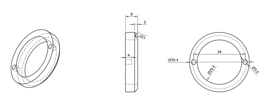
OD should not be critical at all in this case as there’s nothing around the outside for it to interfere with. The drawing does show the OD to be 39 and change
Thinking about this a bit more I think a divot and a grub screw would be a better way to retain it than threading. With two threaded rods going into it there’s the potential unless it’s lockted in place for each of them to rotate. I know in normal operation it’s held in place by a set screw at the top but I think it will be better with one at the bottom also
The tolerances are very loose for the most part. Probably at least +/- 2mm on everything but the rod holes.
Yep, could do either. I’ve got plenty of extra material.
That would work, too. In either case I’d probably thread-lock it to prevent it from vibrating loose. It is currently held at the top by a couple of C-clips in somewhat poorly cut grooves.
If you have a file for it, I could probably print it on my Mars in Jeweler’s Resin, then cast it in aluminum. You’d probably have to drill out and tap any mounting holes, though.
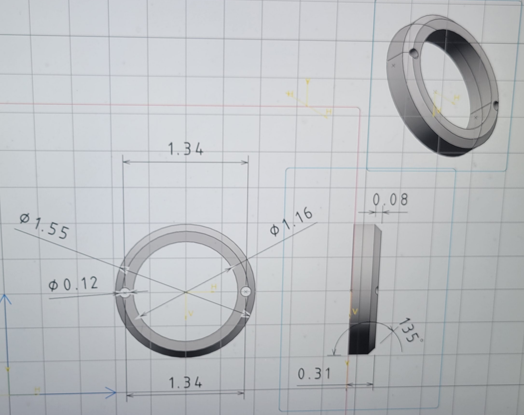
Nice effort, but you have misinterpreted the original drawing. If you notice the hidden line for the blind holes start on the flat side, not the side with the chamfer. Also, it would be advisable to work to at least thousandths versus ten-thousandths. Actual hole size, for example is 3 mm, which is 0.1181". Rounding to 0.12" yield’s a hole bigger than desired. In the case of this part none of the dimensions are extremely critical. Even the hole location is not super critical. But best practice dictates that it is better to work to higher precision than lower.
If you zoom in on the original you will see that the holes do not even line up with the hidden line the hidden line is where the chamfer is located. as for tolerance I kept in mind that it was not critical and just did a 2 place call out. I can agree industry’s standards for holes are 3place but I just made a choice. Anyhow hope this helps clear up what I did just trying to help!
@Frank The main difference is that your holes go through the part whereas mine are blind. David was referring to the hidden lines in the middle of the center image where the 4mm depth is shown.
I don’t have a 3 mm or #31 drill here at the house. I need to get my open enrollment stuff done so I’ll bring it in and put it on the laser and let you drill the holes to size. There isn’t enough meat to put set screws radially. Tapping holes this shallow would require a bottoming tap so I guess glue or loctite the rods in. If they don’t want to stay put, we can put some set screws in at 90 degrees to a radial line through the holes.