I bought a lighted mirror for my bathroom remodel. You should know that I often set criteria I want something to meet and it will make no sense why. It is what it is. This mirror was one of the only models that fit in the space for it. And it was the least expensive by far. I don’t expect the other models to behave any better.
Anyway, this mirror has a touch sensor on the front of it that lights blue when the perimeter LEDs are off and white when they are on. When power is first applied, the mirror is in the off state and the LED is blue. Touch the sensor and it turns white and the LEDs come on. Pretty simple, and just fine for most people, I am sure.
However, that’s not what I want it to do. I want the LEDs to come on when power is applied through the bathroom light switch. I also want the indicator LED to work in its current manner. So, my thoughts are to swap the white and blue indicator LEDs so when power is first applied, the white LED lights. The other half of this is, even though the sensor/controller thinks it should be in the off state, I want the main LEDs to be on. Touching the sensor will turn them off.
So, I’m thinking an inverted signal to drive another device to control the lights. The sensor thinks it is off, but with it off, the LEDs are on, and vice versa. If I use a high current opamp as a comparator, in theory, the opamp could drive the 3A circuit on its own. I don’t know if that’s a good idea or not. The other idea would be to use a FET to control the 12V or GND feed to the main LEDs.
Trying to keep this relatively simple (the circuit has a dimming function, but I am not going to use it), how would y’all go about doing this?
As an alternative, does anybody know of a sensor like this that works in the opposite manner? This one is similar to what is in the mirror, but doesn’t mention dimming.
Partial answer is that potentially the IC in the circuit already to control the state may have both inverting and non-inverting output. If so, cutting a trace, peeling it up and tack soldering to the other output pin should accomplish the opposite power on behavior you want.
Really you could use an op amp driving a transistor to invert the signal, but that may be a current driver on those leds. So if it’s open (transistor is off) its going to maximize the voltage on that circuit trying to keep a constant current. Then when you touch it, it will cut the current off completely.
I would look at the datasheet for the sensor ic and look for opportunities there. Keep us posted!
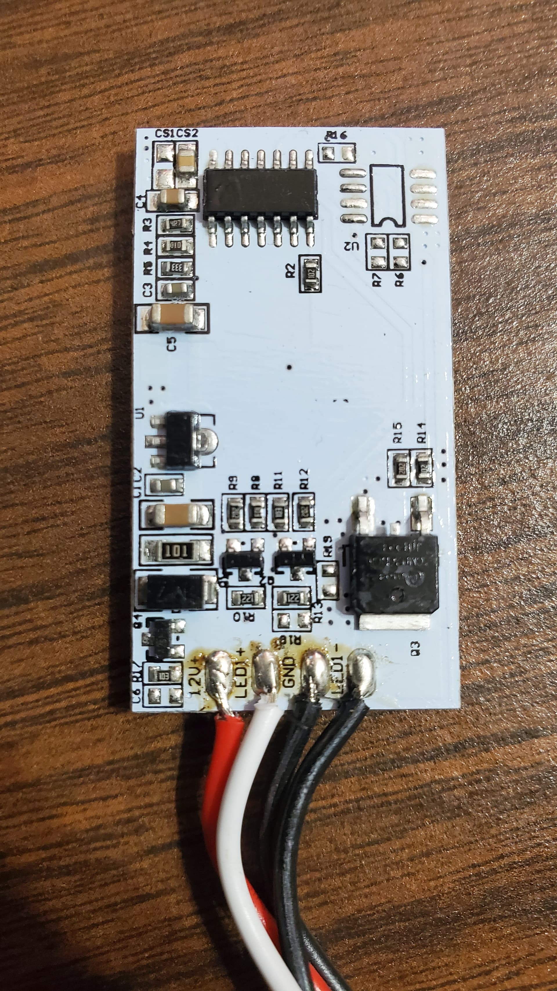
It’s a standard OTS LED light strip operating off of 12VDC. Did I mention this is a cheap one? TBF, though, even the nice mirrors I see in hotels look like they have a standard cut to length LED light strip wrapped around them, so maybe that’s not the cheap factor.
The text on the back of the board is just the info from the chip. From what I can tell, only the two LEDs are on the back of the board with the touch sensor. I don’t want damage the sensor tearing it off of the board.
I have a bunch going on right now trying to get the bathroom to the point where I can rip out all of the dwv and reinstall. One bathroom in the house so it all has to be staged and happen at the same time, hopefully tomorrow. If I can get some free time, I’ll break out the scope and reverse engineer it and go from there. Maybe it’ll show me something helpful.
something to keep in mind is that this won’t be powered all the time. The idea is to wire it into the lighting circuit, so it will only have power when the lights are turned on. I’d rather not have to run constant power to the light also. So, while there needs to be some smarts built into the circuit, it needs to come up ready to use as soon as power is applied. Also note, the touch sensor is non-contact. It resides behind the glass, so any sensor that is used will have to fit into that scenario. I’ve not used and ESP before, so I’ll have to do a bit of reading to understand them.
I decided to get out the scope and have a look at this thing.
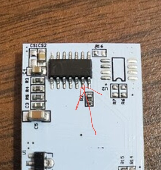
the following pins on the big chip are 0 V all the time:
1, 2, 3, 7, 10, 13
Pin 8 has about +1 VDC on it all the time.
Pin 11 is +5 V all the time, and would appear to be the supply for the chip.
Pin 14 seems to be the sense input.
Pin 12 seems to be the sense return.
Touching either of these pins with the scope probe turns on the light.
Pin 9 is the output. The output is a PWM signal going from 0 to +5 V at about 15 kHz.
Pins 4 and 5 alternate 0 and +5 V depending on the state, and I believe these are driving the blue and white LEDs on the board itself that shine through the mirror to indicate on or off.
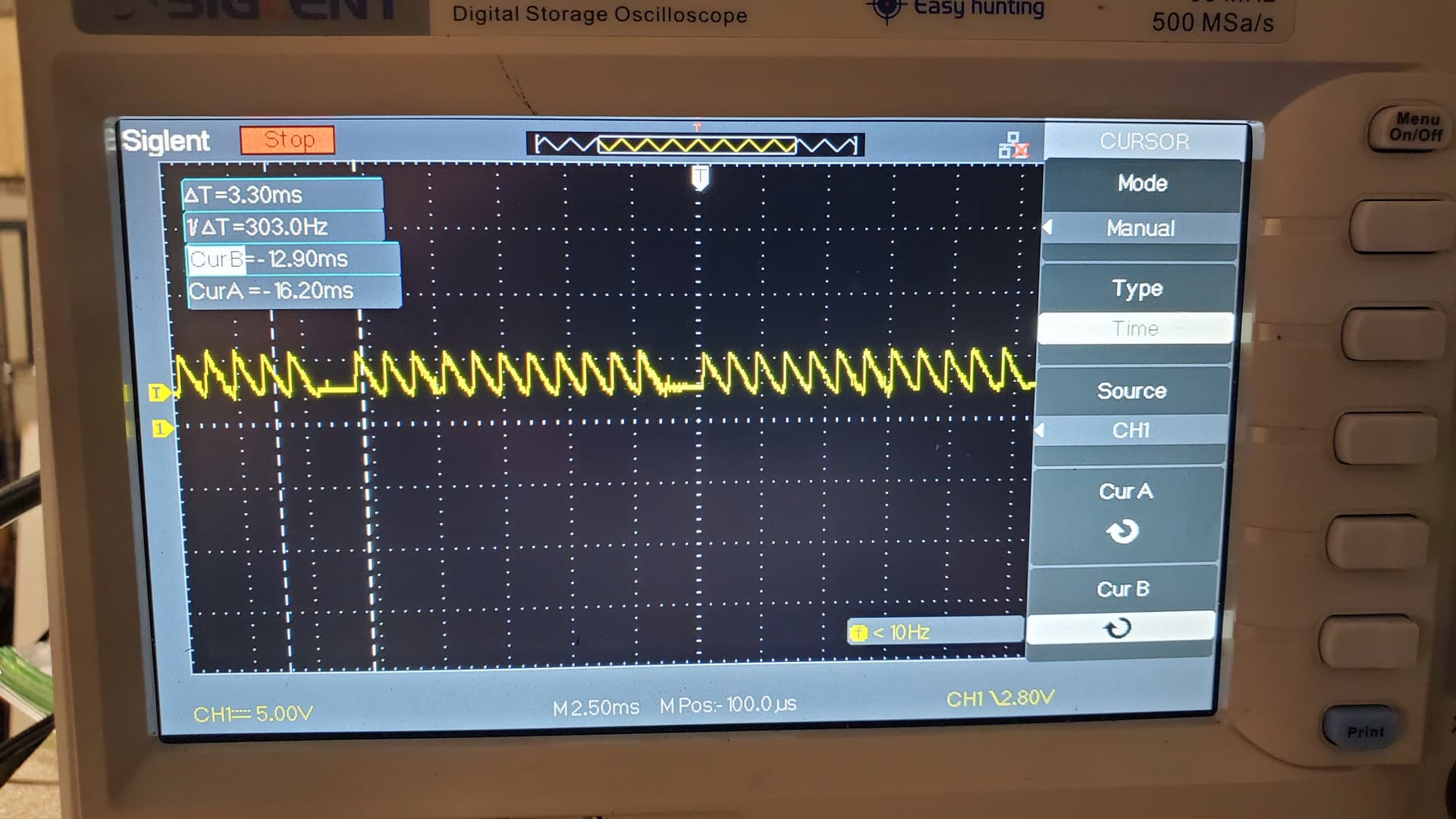
Pin 6 is 0 V when off, but when on goes to a ramp. See picture. I don’t know what this signal does, as it doesn’t change when I brighten or dim the lights.
I suppose any of the lines that are 0 could be ground or could be an input that sets the initial state. I don’t think I want to burn up the board finding out.
It looks like the easiest way to change the mirror’s functionality would be to swap the blue and white LEDs and then use the white LED to drive the FET (Q3).
The output from the board is a constant +12 VDC on the white wire, and the LED ground is PWM to control on/off and brightness.
Think Arduino with Wifi. They’re a little more complex, and they are 3.3v for IO, but pretty easy to pick up, especially if you’ve played with Arduinos. For the sensor, rather than a non-contact touch sensor, you might be able to use an IR obstacle avoidance sensor through the glass, if the glass doesn’t block IR. I’ve got a bunch, so if you want to play with them, let me know and I’ll drop one or two off for you. I could drop an ESP8266 off for you too, for that matter. One big plus to an ESP is that you can add all kinds of functionality to it later if you like. And like I said, they’re dirt cheap.
It looks like I’m going to need a lesson on ESP use. I was thinking of it like a micro-controller that would need time to boot up, but maybe that isn’t a factor. I am a hardware guy. Logic gates, FETs, etc - I get those. I understand software, but I’m not what I would call good at it. I really don’t need this thing to be super fancy. I just want it to light up when the bathroom lights are turned on, but be able to be turned off by pressing the mirror. If not for the visible “switch” on the glass, I would be fine with it just being on all the time.
So, thinking more on this, and seeing how the current mirror works, maybe I’ll just put it up the way it is and start designing my own. I’ve not sand blasted a mirror yet but it sounds like a fun thing to do. Then I can design the mirror to work the way I want from the start, or maybe just have it on any time the over head lights are on.
You can make it a smart mirror, and have it tell you how handsome and smart you are every morning. If someone else uses it, it can tell them they’re ugly losers or something.
I’d be the top candidate for that. Well, except for Christian, James Seymour, James Lancaster, Dominic Canare, John Harrison, and a tiny list of 30 or 35 others or so who are smarter and more qualified. But beyond that…absolutely the top of the list.
You can make it a smart mirror, and have it tell you how handsome and smart you are every morning. If someone else uses it, it can tell them they’re ugly losers or something