I’m working on repairing a lightning damaged Pi. Normally I probably wouldn’t bother, but they are a lot harder to come by at a reasonable price these days. I thought somebody might be interested in the process, so I figured I’d write something up here.
I couldn’t find any visibly damaged components, so I started off by plugging in a known good power supply. No lights, and several components started getting mighty toasty. That’s generally a good place to start, so I removed them:
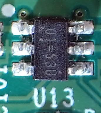
U13, a current limited switch for the USB output power
U9, a switch for the HDMI 5v rail
D13, a TVS diode to protect against high input voltage
None of these parts seemed critical for basic operation so replacing them shouldn’t be necessary to get the board to boot.
Next I used a multi-meter to test for shorts on the power rails. The 5 volt rail was good, but the 3.3 volt was shorted to ground. Generally a bad thing.
I removed the voltage regulator (U3) and several capacitors and other components that could have been causing the short, but no luck.
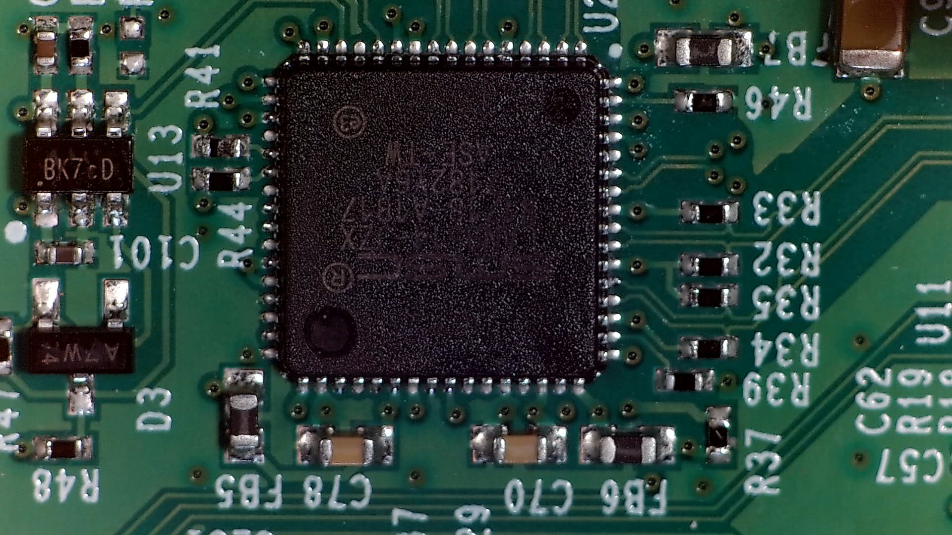
I then removed the USB/Ethernet controller IC (U2) since it was suspected that the lightning strike traveled through the Ethernet, and I had already found one bad component in that area. This cleared the short on the 3.3v rail. Yay!
I replaced the voltage regulator and capacitors I had removed earlier, plugged it back in, and saw a happy little power light. The 5v rail was good, the 3.3v rail was good, the 1.8v rail was… at 3.5v. Not good.
At this point I was pretty sure the CPU was toast; they usually aren’t very tolerant of excessive voltage.
I went ahead and swapped the voltage regulator with one from a Pi Zero that I had fried by introducing an output pin to 5 volts. I checked that all the power rails were good, then inserted an SD card and crossed my fingers.
Lo and behold, the activity light began to blink!
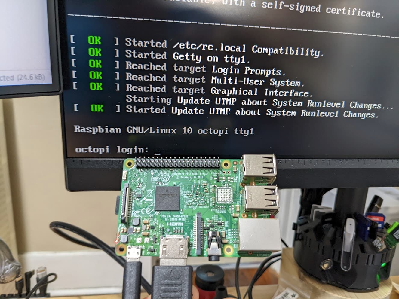
I scavenged U9 from another toasted board so that I could check the HDMI output and see if it was actually booting. I was greeted with a lovely scroll of text proving that the Pi was alive!
This was great, but without USB or Ethernet, I had no way to interface with the board. I had tried to configure the WiFi when I set up the SD card, but that didn’t seem to be functioning either. The previous owner had gotten it second-hand and wasn’t able to get the WiFi to work, so I suspect that component may have been broken previously.
The next step will be to swap out the USB/Ethernet controller from my donor Pi and see if that works.
Fyi, you may already know this but if you take the + lead of your multimeter and put it on a ground pin of an IC, set the multimeter to diode drop mode, you can touch the other pins to see if the pin is shorted to ground (0v) blown open (inf) or healthy diode drop (.4-.7v) this is a quick measure of the esd diodes inside the chip. If it’s open the pin may still work but I wouldn’t trust it with much. If it’s short that pin needs a fork. It is done.
Note to self: get suction tool to help lift ICs with large thermal pads. Tweezers didn’t have quite enough grip on the flat package to overcome the suction from the pool of solder beneath the chip.
Replaced some other small components (R41, R44, R46, FB7) that I had knocked off while struggling to pull up U2. Woops
Plugged in power and Ethernet and was greeted with more blinky lights on the network port. I was able to see the new connection on my router and use SSH to connect to it.
Out of curiosity I played with the WiFi settings a bit and found that the wireless interface was being detected. The issue was that this version of the Pi 3 did not support 5Ghz networks. Connecting to the 2.4Ghz network proved that the WiFi chip was fine after all.
Now the last task was to get the USB working. Plugging in a USB drive had no effect, but I expected this because I had removed the component that controlled power to the USB ports.
I confirmed by probing PP27 that there was in fact no power going to the ports.
Removed U13 from the donor board, struggled for a bit to determine the correct orientation, then soldered it to my patient.
Seriously, what is up with these markings?
Once the Pi booted up again I plugged my USB drive back in and it lit up and was visible from the command line.
Ran some updates over WiFi which worked with no problems.
Swapped in the TVS diode (D5) from the donor board and made sure nothing was overheating anymore.
At this point everything is looking good, so I’m going to tentatively call this a success. I plan to hook it up to a 3D printer, get it configured, and see what happens.
I think I got this one working, but I’ll keep that in mind just in case.
Yeah, that’s good info. I considered testing U2 before removing it, but then I figured that pulling it off the board would be quicker than probing around on a 64-pin QFN package.
The best sharp probe arrangement I’m aware of is to use a hook clip meter lead with a hypodermic needle clipped into it. Or, you can remove the probe end of a meter lead and use a crimped splice to a hardened steel needle.
There are needle sharp meter probes sold, usually as part of a set, and usually not cheaply priced. But many of them are plated brass and easily bent or broken.
Using steel or stainless steel does have higher electrical resistance, but not much more and the durability is worth (very rarely) having to compensate for probe resistance.