Fablab AC

Roy (@Woodman ?) and someone else (I apologize, I’d recognize who but I’m bad with names) fixed the AC in the Fablab. After looking for a while, and finding the right breaker. Woo!

The dial was broken as well. So I designed a very quick one and printed it. It doesn’t fit quite right, so you have to go by ‘clicks’ and not the orientation of the line on it.

However, in turning it off I also tripped the breaker, it seems like when turning to 'high cool, so I’d avoid that particular setting. I left a sign with that, but for anyone wanting to turn that on, turn it clockwise to turn on to get to medium cool (3 or 4 clicks), and when turning it off turn it counter-clockwise back to OFF.

(The breaker # is on the sign in small print if you do mess up.)

Make sure you turn it off when you leave, of course.

1 Like

Sounds like too much inrush current for the breaker to handle. Might want to calculate that and maybe go up a size on your breaker depending on calculations.

@jameslancaster

I will be there tonight and can run calcs.

My guess is that it’s something like that. (It’s old, and the School system did it so it’s 15 years min? (but has a much lower runtime.) so my guess is that it’s drawing something slightly higher.

As per the posted settings it’s supposed to be on medium. (Possibly because of that?)

Oh and if anyone wants to modify it and reprint the knob so it fits better, or has a use to replace some knob, it was a very quick OpenSCAD file, it’s on the Fablab 3D printer computer, in documents/for-fablab, There’s a line that’s a translation before a cube, and the amount can be reduced a bit and it should make it tighter. Eh, I make one that’s better. Feel free to use it.


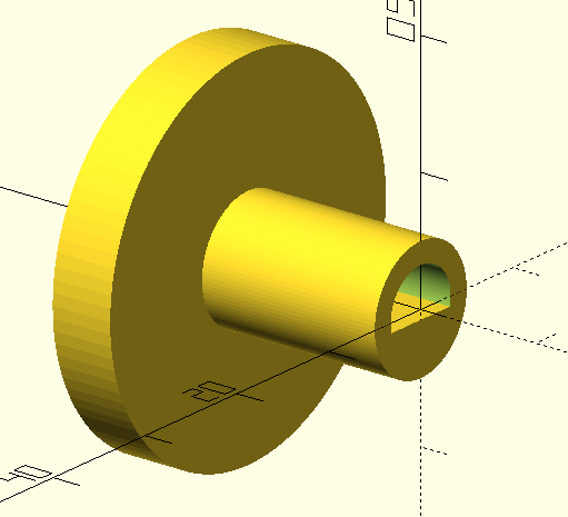
Quick OpenSCAD file for a dial on a peg with flat. I’ve commented it, to help anyone get started with OpenSCAD. To make it, simply open OpenSCAD, copy the text below, Hit F5 for preview, then F6 to compile, and then File-Export. To adjust parameters, simply change them, ex, the peg_diameter to 6, just follow the preview/compile/export.

(I couldn’t measure it too well, I got that the peg was 6.5mm and 4mm flat to opposite side, I think I screwed up the math, but 4mm seems maybe too little?)


// All units mm
peg_diameter=6.5; //Check since you can reorient it
Flat_to_other_side=4; //Check, one side of caliper on flat the other on the round part opposite. 
peg_height=15; //how tall is the peg 
peg_hole_diameter=10; //For the hole the peg is in, how big is the diameter?
dial_OD=30;
dial_height=5;
$fn=100; //This sets how many faces, for things like cylinders, set to how many sides, 100 is pretty good for mostly round things, higher is generally better (more faces to approximate the cylinder) but takes longer to render. You can do some tricks with it, for example if you want a hex, you can set it to $fn=6; (Not recommended in this case.) For grins, I set this at 1000, and rendering times for 100: 1 second, 1000: 18 seconds, and there are only 3 cylinders in this. 


rotate([0,90,0]) { //Rotate so the flat side is down for printing
union(){
    difference (){
        cylinder (d=peg_hole_diameter, h=peg_height); //This is the outer cylinder from which we'll subtract basically the pin.
	translate([0,0,-0.01]){ //Cleanup preview
        difference(){ //Model for the pin, a cylinder, minus a cube 
            cylinder(d=peg_diameter, h=peg_height);
            translate([Flat_to_other_side-peg_diameter/2,-peg_diameter*2,-0.01]){ 
                cube([peg_diameter*4,peg_diameter*4,peg_height+1]);
            }
        }}
    }
    translate([0,0,peg_height]){ //Dial on top
        cylinder(d=dial_OD, h=dial_height);
    }
}}

image

1 Like

I think a metal knob would last longer, but it’s for FabLab so it really should be 3D printed!

1 Like

The other person that worked on it was Joe. He was the main force in fixing it, I just helped.

1 Like

It is not advisable to just size up a breaker without calculating amperage draw for proper wire size. Please contact someone in Facilities for assistance.

With some circuits, it’s acceptable, like for a welding circuit, where the peak current draw is short-lived. I’m not sure if that would apply to this situation. Something else to consider though is whether the breaker could be worn out and tripping below the rated current.

I totally agree, that is what ibam suggesting. If the breaker is weak it needs replaced, and if it’s not sized correctly it also needs replaced. So either way, but beforehand calculations need to be ran.

The thing that people need to understand about using a breaker larger than the nominal ampacity of the wire is that it must be a dedicated circuit for that intermittent use.

What size is the motor? That system probably has some sort of thermistor on it. Probably looks like a disc capacitor.

NTC Thermistors start off with a resistance at room ( like say 100ohms) then as power is applied they decrease in resistance (by a coefficient called the B value) so when the motor starts it tries to draw as much current as it can, but the thermistor limits it. Then once its started the thermistor reduces in value to allow more power transfer to the motor.

I overlooked that. Yes, the ampacity of the wire definitely needs to be taken into account. It’s been a while since I designed panels so I’m a bit rusty.

I want to find the info on the AC unit so I can do calls for breaker and thermistor size and ampacitcy of the wire required and see what the current wiring can tolerate.

*Disclaimer: I was an Automation Engineer, not a Residential Electrician. I know there is some overlap and I also know I know enough to know I need to learn more about residential wiring codes.

1 Like

I believe the electrician told us we couldn’t get replacement breakers for the old boxes anyway … but that might have just been the ones in the hallway.

Thanks to you and Joe.